
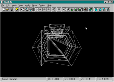
 1) Open the Component (ie Harvpod.dxf or Harvpod.3ds). This has been covered previously.
2) As per normal, start with "MODIFY" "POLYGON" making sure the component is solid and properly oriented. Click "REDUCE VERTEXES" changing "Distance Threshold:" to "0.0001" to merge any vertexes or points that are VERY close together (almost overlapping) and make sure all the polygons in that area link to one point, hopefully removing any holes or polygon overlaps. Click "REDUCE POLYGONS" to remove any duplicate, overlapping or coplanar polygons, potentially reducing several surfaces to one. Make sure "Polygon Size" is set to 3 to ensure that all polygons are 3 sided. Finally click "AUTOFLIP POLYGONS" to ensure that the polygons are set to the correct orientation. (DXF, 3DS, and many other formats are not sensitive to polygon orientation. Lightwave, some VRML browsers, and some other programs are!). The object is now properly prepared for applying the image maps.

3) Break Apart the Pods and the Girdir.
We now add a new process to the sequence. The "harvpod.dxf/harvpod.3ds" component actually consists of two distinct objects, the Cargo Pods themselves, and the Girder that connects them. For added flexibility when combining with other components, and to easily apply the two separate image maps (harvpod.jpg and harvgir.jpg) we are going to break the combined component apart. First rotate around to the side of the object, and up a little bit to where we can just see across the top of the Cargo Pods, and the Girder is above our line of view. Then we need to switch into "Edit" mode by clicking on the hammer button.
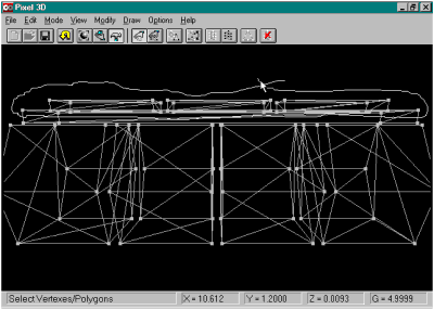
Switching to this mode brings up a new set of tools on the toolbar. Immediately upon switching into "Edit" mode by default we have the "Select Vertexes" tool selected. We can select vertexes by clicking on them one by one (vertexes turn white when they are "selected") or we can do a "group select" by drawing a "lasso" around the vertexes we want to work with. In this instance, draw a line around the vertexes in the Girder. Be careful NOT to select any of the vertexes belonging to any of the Cargo Pods. Don't worry if you miss a few as there is another command that will add in the vertexes we missed.

Now click the "Select Linked Vertexes" button which will select all the vertexes that are directly linked to the vertexes we have already selected. This will select those vertexes that were adjacent to the Cargo Pods without selecting any of the vertexes on the Cargo Pods by accident.

We now have selected all the vertexes belonging to the Girder (and indirectly all the associated polygons as well). Note that the selected vertexes are white while the remainder are grey.
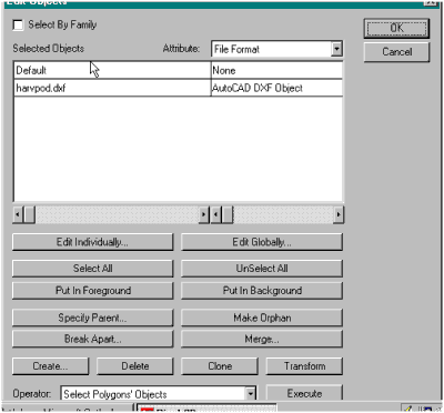
Now we go to the "MODIFY OBJECTS" menu item. In this menu we work with grouped polygons refered to as "named objects". Highlight the "harvpod.dxf" line, and then click the "Break Apart" button.
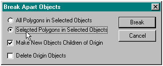
We want to split off the vertexes/polygons belonging to the Girder without affecting the remainder of the object (the Cargo Pods). We therefore choose the "Selected Vertexes in Selected Objects" option. In addition, we would like the Girder to stay associated somewhat with the Cargo Pods, so check the "Make New Objects Children of Origin". We don't want the Cargo Pods deleted, so don't check the final box.

The process has now split off the selected vertexes, and grouped them into several independent objects titled "harvpod.dxf Sub1" through "harvpod.dxf Sub4". The Cargo Pods make up the original object, still titled "harvpod.dxf".

Now we need to combine the 4 individual child objects into one object, the complete Girder component. Pixel 3D has us select the components to be joined into another object, so we have to be careful how we group select the components. In this case, we want to merge "Sub2" through "Sub4" into "Sub1". Highlight "Sub2", "Sub3", and "Sub4" and click the "Merge" button.

In the "Merge Objects" requester, we want to choose "Transform, Position, and Merge" to keep all objects in their original locations ("Simple Merge" would pull each object to a common center point while merging them), and to replace the original components ("Sub1" through "Sub4") with the new combined Girder by leaving the "Delete Original Components" checked.

This is what we are attempting to do, so click "Yes".

We now have successfully split the Girder off from the Cargo Pods.

Just for clarities sake, rename "harvpod.dxf Sub1" to "Harvest Girder" to avoid any later confusion.

4) Choose "MODIFY" "SURFACE": We now want to apply the appropriate BMP image maps to the appropriate surfaces of these objects. At the "MODIFY" -> "SURFACE" menu, highlight "DXF Color 7 (1)" and click "Edit Individually". The Surface Editing screen appears.

Change the name to "Harvest Pods" to differentiate this surface for when we combine these objects with other components.
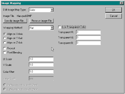
Now click "Image Mapping". Click "Specify Image File", and choose the appropriate BMP image file (Harvpod.bmp in this instance).
By looking at the original image file, we can see it needs to be mapped or applied from the side. Click "Align on X-Axis" to see if this will give us the correct orientation. Be sure to set "U Scale", "V Scale", and "Color Filter" to "1.0".

Change the name of surface "DXF Color 7 (2)" to "Harvest Girder", as this is the surface we will use to apply the Girder's image map.

Now click "Image Mapping". Click "Specify Image File", and choose the appropriate BMP image file (Harvgir.bmp in this instance).
By looking at the original image file, we can see it needs to be mapped or applied from the top. Click "Align on Z-Axis" to give us the correct orientation. Be sure again to set "U Scale", "V Scale", and "Color Filter" to "1.0".
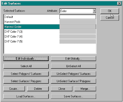
We now have the two surfaces containing the Cargo Pod and Girder image maps. Later we can come back and delete the 3 extra surfaces (DXF Color 7 (3), (4) and (5).), but for now leave them alone.

We want to apply the Girder Surface (image map) to the Girder Polygons. Go back to the "MODIFY POLYGONS" menu. Change the settings to "Selected Polygons" from "All Polygons" as we currently have the Girder Polygons selected. Click the "Apply Surface" button

Choose the "Harvest Girder" Surface from the selection and "Apply".
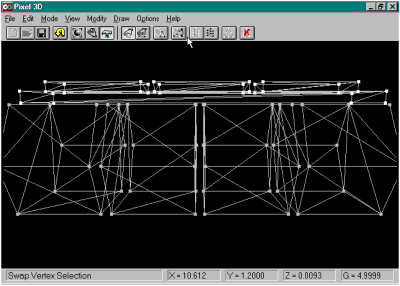
Now we need to switch from the Girder to the Cargo Pods and apply their Surface (image map). "Okay" out of the "Modify Polygons" menu. Now back in "Edit" mode there is a quick way to "Unselect" all the Girder Vertexes and "Select" all the Cargo Pod Vertexes. Click the "Swap Vertex Selection" button.

Viola! All the Girder Vertexes have changed back to grey and all the Cargo Pod Vertexes have changed to white, indicating they are "Selected".

Go back to the "MODIFY POLYGONS" menu. This time it is the Cargo Pod Vertexes that are selected. "Apply Surface" to these selected vertexes/polygons to overlay the "Harvest Pods" Surface on them.
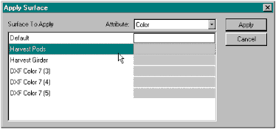
Choose the "Harvest Pod" surface this time and "Apply".

5) Time to go see the final effect. Choose "Phong Shading to see how the image maps have been applied to the object. You may note that in some areas the image maps are not displayed clearly. This problem is being worked on.
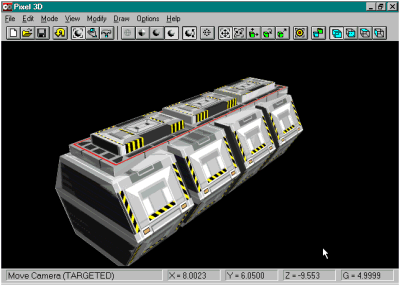
7) Save The Component/Object in Pixel 3D Format
Save this component in a format that will keep the texture map and other changes we have made. Click "Save", choose "Pixel 3D" as format, and change the file extension to match ("Harvpod.p3d" is what I used).