for use in a motordriver circuit
Aart Jochem
aartj@yahoo.com
16 august 1993
Abstract: this document describes the design of a simple D/A-converter to use in a mobile robot project in the motordriver circuit. The aim is to have different speed levels of the robot, forward and backward. The circuit is build and tested in my Tattletale based robot project [1]

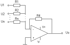
In the figure above the basic D/A-converter circuit is shown. The output of the opamp is determined by the input voltages and the ratio between the feedback resistor R4 and the input resistor as follows:
![]()
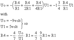
In the case of the Tattletale based robot, 3 bits are used to indicate the 8 output levels for the H-bridge (as in figure 2 below). This is used to drive a DC-motor. The 8 output levels correspond thus with 8 speed levels of the robot. The formula above is used to calculate the proper values of the resistors.
V+ and V- determine the maximum and minimum output voltage of the opamp. In my case it is + and - 9 volts. The input voltages are 5 volts (a logical 1 on TTL-level). I chose U3 the least significant input bit and U1 the most significant bit. This is why R2 = 2 R1 and R3 = 4R1.
 <
<
If I choose R1 = 47k, then R2 = 100k, R3 = 200k and R4 = 47k. I don't need 8 speed levels forward, so I added a potentiometer to the +-input of the opamp and V+ and V-. Now I can adjust the the levels backward, stop and forward in the following way: make the input 010, adjust the potmeter until the output level is 0 volt (or the motors stop turning) and I have 2 speed levels backward and 5 levels forward.
The complete circuit is shown in figure 2.

[1] http://geocities.datacellar.net/Area51/Lair/6412/robo/robo.htm