|
Introduction:
Maxidecoder v1.0 is a very cheap ( about 15 US$ ) easy to build decoder for cable TV networks using syncronisation coding.
The only limit to this decoder is that you need a device ( TV or Video ) with a scart interface to use this decoder.
Iíve tested it at the Swedish network ĒKabelvisionenĒ with great results. It should also work at ĒTeliaĒ and ĒSvenska Kabel TVĒ.
It manages to decode all 28 channels ĒKabelvisionenĒ is offering including Filmnet 1 & 2,
TV1000, TV1000 Cinema and Hallmark.
Function description:
There are many was to code a TV signal. Some companies use a signal that scrambles the TV signal and are removed with a Ēmid passĒ filter. Such a picture are recognized by itís stable but not very nice to look at. Maxidecoder v1.0 doesnít decode this kind of signal.
Another way to code a TV signal is to manipulate with the signal's syncronisation and polarity. The coded picture may roll and you canít see a thing. You canít hear anything eigther. When the picture ainít syncronised, the TV won't know where the picture starts or ends. Maxidecoder v1.0 is made for this.
Components:
IC 1		1	Logical unit. 4069 ( 14 legs )

IC2		1	Logical unit. 4538 ( 16 legs )

p1, p3		2	Potentiometer 22kW or 25kW

p2		1	Potentiometer 10kW

p4		1	Potentiometer 100kW

p5		1	Potentiometer 2,2M or 2,5MW

p6		1	Potentiometer 100W

r1,r6		2	Resistor 100kW

r2		1	Resistor 10kW

r3		1	Resistor 56kW

r4		1	Resistor 47kW

r5		1	Resistor 18kW

r7		1	Resistor 6,2kW

r8		1	Resistor 22kW

r9		1	Resistor 47W

c1		1	Ajustable Capasitor 15p

c2		1	Capasitor 1000 pf

c3, c4, c7	3	Capasitor100pf

c5, c8		2	Capasitor 2200 pf

c6		1	Capasitor 68 pf

d1, d2, d3, d4	4	Diod 4148

Scart connector	1

RF contacts	2	Male, Female
How to build it:
1. Solder the two ICís.
2. Solder all potentiometers.
3. Solder all capasitors.
4. Solder all resistors.
5. Solder all diods.
6. Connect a 6 -12V DC supply or a 9V batteri connector.
7. Attach the scart connector.
8. Solder the koax cable and the RF connectors.
9. Jump high and hope youíve got all at the right palce.
How to connect it:
This decoder may be connected to a TV or Video that are equipped with a scart connector.
Make sure that you connect the koax and the scart connector to the same device. It wont work unless. Connect the antenna to the decoder.
Test and adjustment:
Note:
Donít proceed with the next step until the recent one is finnished.
1. Power on the decoder. Switch to a UNCODED channel. Adjust the TV to normal brigthness. Make the following adjustments:
p1 fully to the right, p2 centerd, p3 centerd, p4 fully to the right, p5 fully to th left, p5 fully to the right and c1 centerd.
2. When you are finnished with this step, youíll have a brigth wide line over the screen.
Turn p2 until you have a stable picture. If you canít get it stable, try adjusting p3 a bit and then p2 again.
3. When you are finnished with this step, the wide line will be gone but the picture is brigther than before.
Turn p4 until the wide line just dissapear to the left. If you canít see the left edge, turn p4 fully left and then turn it back until it dissapers.
Turn p1 until the rigth edge dissapears to the right.
4. Adjust p5 until the distortions in the top of the sceen just dissapears.
5. Switch to an CODED channel. Turn p6 fully left. Adjust c1 until the coded channel appears. Note that the picture may dissapear when you touch c1 with a iron screwdriver.
Turn to another coded channel and adjust c1 until it appears.
Now you have to get true all coded channels and find the right setting for c1.
When this is done, you can adjust the coded channels brigthness with p6. Here you will have to compromise besauce you canít get the same brightness at all channels, the decoder ainít that good yet.
When itís not working:
∑ The picture has totaly disapeard.
If you heavenít got any picture at any coded channel itís probably p2 that needs an adjustment.
If this ainít working, try increase the brigthness with p6 and if this ainít working try c1.
∑ The picture is unstable at the top.
Try p2 and if that ainít working at all try p5. If nothing of this works, try turn p3 a little bit more to the right.
∑ The picture is unstable in the sides.
Turn up p6. if this doesnít work, try p4 or p3.
∑ Prolems when connecting it to another TV or Video.
Adjust p3 for the incoming signal level, and p6 / c1 for the brightness.
∑ The picture is to bright.
Is it an uncoded cannel ? If it is, switch off the decoder and if not, adjust p6 / c1.
∑ I canít get the autosearch to stop at a coded channel.
Try adjust p6 / c1 for maximum brightness. It will find the cannels easier then.
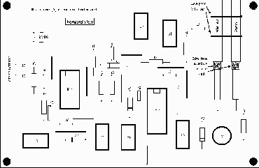
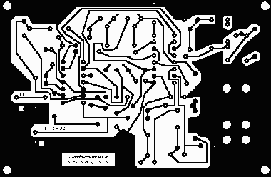
Original PCB and Board Layout


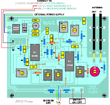
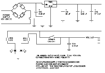
New PCB for board layout and Power Supply


|