|
This Video Descrambler circuit is intended for experimental purposes only.
It descrambles suppressed sync video mode only, audio is not touched. Gives a good picture with some dispersion present. Video input is 1 volt p/p and output is 1 volt p/p (adjustable).
Because of the critical time pulse adjustments, a scope should be used (that can handle video).
Parts are easily aquired (some are Radio Shack).
Contents:
1. Colour burst Detector and Horizontal timing pulse generator.
2. Horizontal lock/phase generator and Horizontal Sync generator.
3. Vertical timing pulse generator.
4. Video amplifier and Sync processor.
5. Power supply. (not present as yet)
6. Circuit description.
7. Scope (Optional)
Colour Burst Detector & Horizontal Pulse Timing
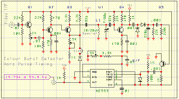
The Video input at point "A" is emitter followed (Q1) and amplified by Q2, then direct coupled to gating transistor Q3. The colour burst portion of the Video signal is detected by a tuned circuit, consisting of L1, trimmer capacitor and associated 82 pf capacitors. Transistor Q4 amplifies the colour burst, and can be seen at Tp1.
Colour burst adjustment is made by adjusting slug in L1 and trimmer capacitor, these adjustments are performed with Q1 and Q3 pots set to mid range and the link at Q3 open. This is the most importent adjustment of the entire circuit, as the rest of the circuits follows the colour burst.
The L1 coil or choke can be made by winding app 40" of #36 enamled wire on a 3/16" dia. coil form. The closer the coil/cap are to resonence (3.58mhz) the beter the circuit will work.
Q4 drives the detector diodes (1N914) so that the colour burst is now a 15,750 hz pulse that turns on Q5. Q5 output at Tp2 will now be a negative going pulse, which will also have some white video pulses present. The 15,750 hz pulse is used to gate the NE555 chip whoes output at pin #3 is adjusted for a lock width pulse of 2 us (Tp3). With the link reinstalled the 15,750 hz pulse at Tp2 should now be clean, and the white video pulses gone. Readjustment of the Q1 and Q3 pots should allow channel hopping of scrambled channels, and still have a fairly clean Tp3.
Circuit board output at "B" is as follows:
1: 15,734 hz Horizontal 2 microsecond pulse (Vcc to app 1 volt above ground)
2: 59.9 hz Vertical pulse.
Color Burst Circuit
 Vertical Trigger & Timing Generator
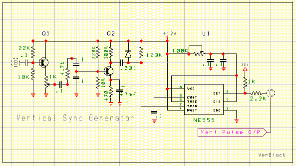
The 59.4 hz pulse from the color burst circuit "B" is feed to Q1 emiter follower, filtered amplified by Q2, shaped and used to turn on U1. The output of U1 is set for Vertical sync width of about 3/4 H (190 microseconds) (Tp1). The output of this circuit is designated as "C".
It should be noted that any timing chip (555 or 556) should have Metal Film capacitors used for there temperature tolerances. NE555 pin # 6/7 and NE556 pin# 2/6 and 1/2.
Vertical Circuit
 Horizontal lock/phase generator and Horizontal Sync generator
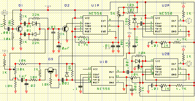
The Horizontal generator circuit uses the 15,750 hz pulse "B" from the colour burst circuit to do all of the timing and phase corrections. Q1, Q2, Q3 and U1A is the Horizontal oscillator.
While scoping Tp2 adjust U1A pot for 15,750 hz while Q3 Horizontal phase pot is set mid range.
Tp2 adjustment can be checked with a freq counter, or viewing the Horz freq on one channel of a dual input scope, with the other scope channel viewing the incoming video suppressed sync pulses.
Or if all else fails, check for Horizontal lock on a monitor or TV.
Pin # 5 of U1A drives Q3 to make a sawtooth ramp at Tp1. DC from the Horizontal phase Pot is added to the ramp and applied to the diodes (1N419). These diodes are being used as a switch for the time of the incoming keying pulse from the colour burst circuit "B" thus a portion of the ramp is removed and filtered and sent to the osc control pin # 3 by Q2. The filtering on Q2 base is used to help stop changes in Horizontal osc frequency by intermittent loss of colour burst.
U1A also drives U1B pin # 8, which is a delay generator used to move didgital audio. This circuit can be set to minimum or not included. U2A and U2B are identical circuits, they generate the Horizontal blanking and Horizontal sync pulses.
Horzontal blanking pulse is set for a width of 7 us (Tp4) (E)
Horzontal sync pulse is set for a width of 5 us (Tp3) (D)
Horizontal Generator Circuit
 Video Processor
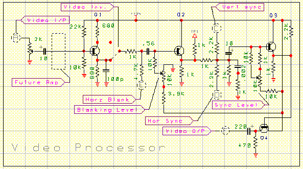
The video at "A" is coupled, frequency compensated and high passed to Q2. Horizontal blanking is mixed with the video and high passed via Q2 to Q3. Sync inputs are mixed with the video at Q3 base, and then feed to the emmiter follower output transistor Q4. Adjustments for the horizontal sync levels are made on the Horizontal generator circuit board. Sync levels should be app 1/3 of the video output wave form. If in dought check a normal video wave form for levels and or timing durations.
Carefull adjusting of all timming pots and colour burst, will give a fairly good picture with some dispersion. Works good for me.
Video Circuit

Notes:
All transistors are common NPN types except for Q1 and Q2 of the Horizontal generator circuit, they are common PNP's.
All diodes are common 1N914 types
IC's are 556 and 555 any manufacture. The two 555's can be a dual 556 if built on one board.
For experimental purposes this circuit was built on three Radio Shack boards #276-162
The power supply is a regulated 12 Volt supply, using a 7812 regulator (filtered).
Cost to build this circuit would be app $80 or zero if you got a junk box of parts.
|