| Textures of Wood |
2. Solving the problem
2.1 Tree growth description
2.2 Tree growth simulation
4. Program management
4.1 Saving picture
5. Program details
5.1 Graphics initialization
5.2 User-computer communication
5.3 Setting color palette, screen
capture, picture transfer
6. Conclusions
7. References
Pine-tree has conical shape with height-to-radius ratio of 80:1.
Radius of first annual ring or thickness of any annual ring in the future
is dependent on tree food supply. Based on observations we can set ring
thickness between 1.5 in 3.5
mm. Part of annual ring growing in spring, when tree has enough food, is
light-colored. Oppositely, the part growing in the fall, quickly changes
to dark colored. Every year new annual ring envelopes te rest of the tree,
and generates numerous branch sources, deviating in direction and height.
As said, tree trunk grows in ratio 80:1, on
the other way branches do in ratio of approximately 32:1.
In addition we must take into consideration the lower fifth of trunk, where
there branches with the thickening of the trunk, die away. Tree cones are
not perfect. Their radius deviates around their theoretical radius with
sine function, amplitude 3 mm, wave length 0.5 m. Because
of obstacles that appear in the vicinity of the tree (walls, other trees),
thickness of annual ring also changes tangentially. According to this,
we can expect maximum of 15% eccentricity
of trunk. On the lower part of trunk we also detect tangential deformation
of raduis because of root effect.
Primarily we generate a random set of annual-ring thicknesses, which
influent set of radii and annual-cone heights. On the top of every annual-cone
we select a random number of branches that will grow there (0-7). Full
circle is then divided into pies depending on branch-number. Every pie
(angle) is then altered by up to +/- 20° randomly. Branche origins
are also moved along the height of the tree by up to +/- 5 cm.
Finally we declare the trunk eccentricity, up to 15 %. Tree is now
defined.
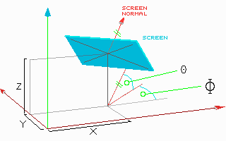
Screen is captured separately for every pixel of screen. We must scan screen rows from top to bottom, and columns from left to right. Coordiantes of every pixel [ij] are transformed to coordinate system of tree [xyz]:
I = (i-320) J = (j-240)
x = X + (sin(j)*I + sin(J)*J* cos(j))*Zoom/320
y = Y - (cos(j)*I - sin(J)*J* sin(j))*Zoom/320
z = Z - (cos(J)*J)*Zoom/320

Numbers 320 and 240 are halves of SVGA mode 640x480.
When [xyz] coordinates of pixel are calculated, we must determine
the color of this pixel.
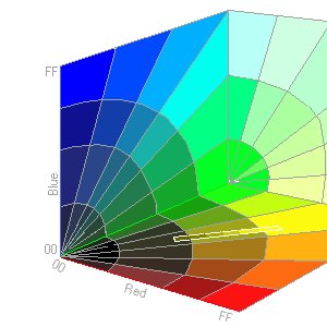
Color palette of pine-tree is found to be a line between RGB points
[68 3C 00] and [D4 A4 2C] hex. I`ve determined these two border colors
by observation (valid only for palette file TreePal0.COL). Considering
the most accurate graphical modes work in 8:8:8 direct color modes, the
Red, Green and Blue axes can be divided up to maximum of 256 integer
values. If we place our line into such a RGB cube, then the line will have
it`s diferentials Dr, Dg and Db. Only in lonsam cases, one or more diferentials
will stretch up to 256 units. These are mainly palettes of clean colors
of red, green, blue, yellow, turquoise, violet and gray. In our case the
span Dr Dg Db is [+108 +104 +44] dec. Because the RGB coordinate system
is integer-based, our line can provide us with maximum of the longes diferenial
plus 1 diferent colors (our case 109 colors). Writing a picture file in
direct color mode would be because of the above reasons wasteful in size,
speed and compressibility. That`s why we chose 256 fixed colors mode 640x480x256.

Color of every pixes is defined by its coordinates [xyz]. Coordinates y and z are transformed into radius from X axis, [r 2]= y 2 + z 2, next to it to the angle y = arctg(y/z) on layer YZ. Based on coordinate x and angle [y] we seek for that last cone, whose radius does not exceed the radius of our pixel from X axis. Dependent on the ratio of distance of pixel from the last cone with respect to the thickness of annual-ring here, we get the percentage of pixel position within annual-ring thickness, where from we derive color index (0% = 255, 100% = 1).
Radius of cone depends on coordinate x: R(x) = (R[i] - (x/80))
Then modified with sine wave: R(x) = R(x) * (1 + (sin(4*P*x)*0.033))
and eccentricity: R(x) = R(x) * (1 + sin(y)*Exc)
Considering the effect of roots dependent on height: R(x) = R(x) * (1 + root*0.3*xx55)
R(x) = R(x) * [mul] is the last factor to
be considered - effect of branch. I`ve simulated branches with local multiplication
of all cones around the branch. Multiplication factor depends on modified
angle [j] between
vector of branch and vector between two points (pixel to branch origin
point on X axis). A starting factor of 1 is multiplied with factors of
all neighboring branches. These are:
if angle [j]
is smaller than 0.65 rad (1 + 32*e-26*j),
else is 1
With all these multiplication factors, we deformed-streched the basic
tree-cones to a shape of tree. The last multiplication factor influences
the color of pixel. Annual-rings inside branches are much more thinner
than in the trunk [0.4 .. 1.2] mm, therefore they are darker. Their color
span is no longer full, so we add color multiplier
Cmul = mul16 , which assures darkening of branches.
002.501 000.050 000.000
001.558 000.000 000.242
TreePal0.COL
Possible problems at run-time are written to a file TREE.ERR. During run-time parameters of intersection layer can be manipulated:
TGA format:
|
|
|
|
|
|
|
|
|
|
|
|
|
|
|
|
|
|
|
|
|
|
|
|
|
|
|
|