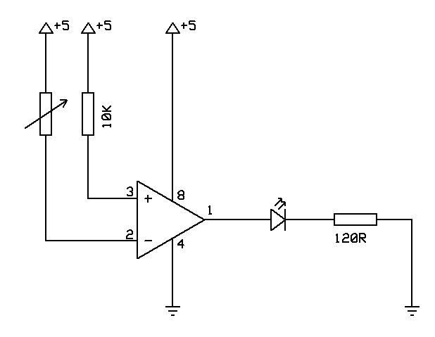
This is a simple project that investigates a voltage comparator. The idea is to use the logic output of a comparator to turn on a LED. One input is wired to +5V through a resistor and the other input is wired to +5V through a variable resistor. By varying the resistance, the LED will turn from off to on (or vice versa).
The circuit diagram for the project is:

The bill of materials is:
| Qty | Item | Rapid Code |
|---|---|---|
| 1 | LM339 Dual Comparator | 82-0272 |
| 1 | 10K LIN POT | 65-0505 |
| 1 | 5mm Red LED | 55-0117 |
| 1 | Resistor | |
| 1 | Resistor | |
| Some 7/0.2 & 1/0.6 wire |
The breadboard looked like this:
See a video of the project in operation.