Back in 1990 I bought a solderless breadboard and some digital ICs with a plan. The plan is long forgotten, but many of the ICs are still with the breadboard. They will be re-used.
The requirements of the project are:
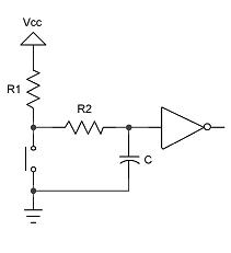
The 74HC74 is a dual D type flip flop, and only one of them is used. The Q and Q output pins light the LEDs, and are driven by the 74HC14 hex invereter. The Q pin also drives the D input pin of the flip flop. The first problem is getting a clean pulse to the flip flop clock input pin CK. The following diagram illustrates the debounce circuit used (and was taken from this excellent debouncing document):
The circuit diagram for this project is:
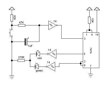
The remaining consideration is what to do with the 4th inverter and what do do with the 2nd flip flop. Pins shouldn't be allowed to float, so they need to be pulled up or pulled down.
The RD (pin 1) and SD (pin 4) need to be High for the flip flop to work with the CK input (pin 3) triggerring the change and they should be pulled up to mark them as High. The trigger uses the High/Low on D (pin 2) to determine whether to set Q (pin 5) High or Low and Q (pin 6) correspondingly Low or High on the leading edge of the CK input (i.e. when there is a change from 0V to +5V). This is why the Q pin is connected to the D pin; if Q is High we want it to go Low when a pulse is received on CK, and vice versa.
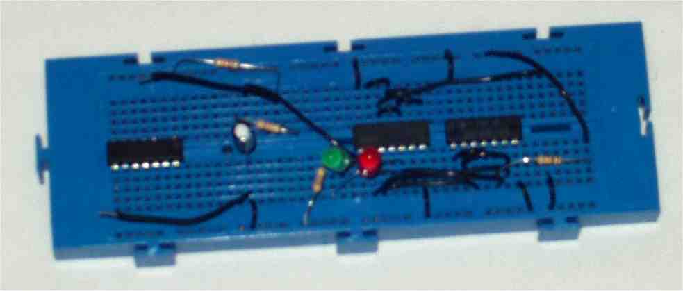
The breadboard looked like this:
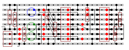
The stripboard plan includes elements to use all spare pins and looked like this:
The final stripboard project, without using the spare pins, looked like this:
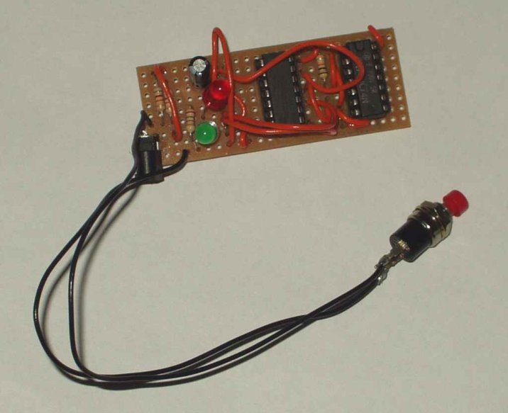
The socket is for the power-in supply.