The plan is to use the 12V 400mA DC supply from a wall-wart as the unregulated supply and convert this to +5V DC regulated.
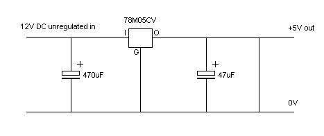
The circuit diagram is:

The bill-of-materials is:
| Qty | Item | Rapid Code |
|---|---|---|
| 1 | 7805 voltage regulator | 47-3556 |
| 1 | 470uF 35V Radial Electrolytic | 11-0360 |
| 1 | 47uF Radial Electrolytic | |
| 1 | 25mm X 64mm stripboard | 34-0500 |
| 1 | 1.3mm DC Power Lead | 20-1030 |
| 4 | M3 Bolt | |
| 4 | M3 Washer | |
| 4 | M3 Spacer Nut | |
| Some 1/0.6 wire |
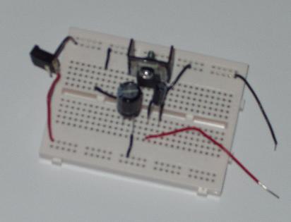
The breadboard looked like this:

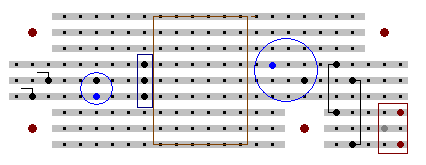
The planned stripboard layout is:

The stripboard layout includes 4 bolt holes for fixing it in a housing.
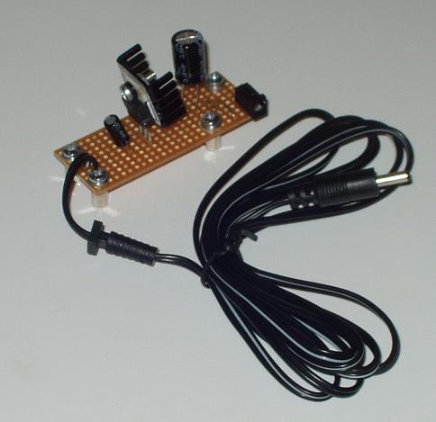
The final project looks like this:

In retrospect, putting a bridge rectifier in the circuit would have 'proofed' it from plugging a reverse polarity or AC source into the input, and an on indicator LED, even though it would have used some of the mA and V.