Originally intended to use a 16F628A or equivalent µController, but instead it uses the 12F629 or 12F675 µControllers (8 pin microchips).
This topic comprises several small projects each with increasing complexity.
The projects use the +5V Regulated Power Supply. The internal 4MHz clock is used for the clock source. These projects are not intended to go beyond the bread-board stage, unless otherwise indicated. The source, compiled HEX file and a video that demonstarates each project in action is available.
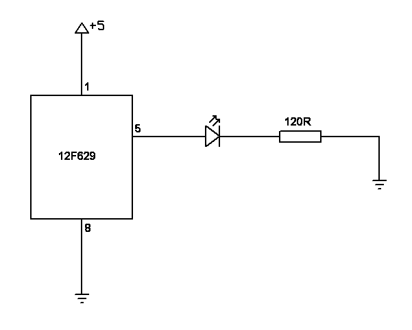
This is the "Hello World" of PIC development. The requirement is to flash an LED on and off. The PIC can source (or sink) up to 25mA on an output, and it drives the LED directly. Control of the ouput is done programmatically. The interval between flashes uses simple programmatic counting. The LED toggles on/off every half second. The project uses the 8 pin 12F629 µController.
Only one of the six I/O pins is used. The other five are not used and are pulled up internally. GP3 does not have an internal pull-up, and is an Input only pin. It is allowed to float (which feels bad so it might be pulled down to ground instead. No prooblem was subsequently found allowing it to float).
The circuit diagram for this is:
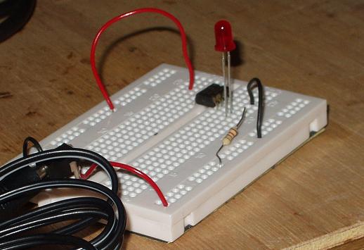
The breadboard looked like this:
The µController instructions used in this project are:
| Instruction | Description |
|---|---|
| GOTO | The µController processes instructions in sequence. This instruction changes the position in the sequence for the next (and subsequent) instruction. |
| RETFIE | When an interrupt occurs, the position in the sequence of instructions is saved, and the position changes to 4, known as the interrupt vector. This instruction restores the position to the saved position. |
| MOVLW | Put the specified byte value into the W register. The W register is a general purpose register that can contain any byte value. |
| MOVWF | Put a copy of the W register into a file register. The RAM of the µController is made of a numbered sequence of bytes. Each byte is a file register. Some of these file registers have special functions. |
| MOVF | Put a copy of the file register into either itself or the W register (i.e. the opposite of MOVWF). |
| DECFSZ | Decrement (reduce by 1) the value contained in the specified file register and skip over the next instruction in the sequence if the new value is zero. |
| BCF | Clear (i.e. set it to logic 0) the specified bit of the specified file register. |
| BSF | Set (i.e. set it to logic 1) the specified bit of the specified file register |
| XORWF | Do a logical exclusive-OR of the bits of the W register and the bits of the specified file register, and put the result in the W register or back into the file register. |
Note: the RETFIE instruction is only included in this project in case an interrupt occurs.
The first instruction a PIC µController processes is at position 0 in the sequence. Since we want it to skip over the interrupt code, the first instruction is a GOTO. "But this project doesn't use interrupts?" When an interrupt occurs, the current position is pushed onto the stack, and the position is set to 4 (the interrupt vector). The instruction at this position is a RETFIE, so if an interrupt occurs for whatever reason, it is handled. As the project is not using interrupts, it can simply return from it. If the interrupt wasn't handled and instead the 'main program code' used position 4, then execution of the sequence would change whenever an unexpected interrupt occurred. By handling the interrupt cleanly, we avoid introducing hard to locate bugs.
The next instructions in the program set or clear various bits of file register bytes to set up the µController for use as indicated by the datasheet.
The program is a loop to turn LED on / off. It does this by oscillating an output pin between logic high and logic low. It uses the XORWF instruction to do this by inverting the bit setting of the output pin switching it between logic high and logic low.
The µController will do this oscillating, flashing the LED on and off, too quickly for the human eye to see.
To slow things down some delay loops are added. These leverage the property that an instruction takes a known amount of time to execute. By creating the loop and calculating how many instructions are executed by the loop, the amount of time the delay will take can be determined.
Download the source code and a compiled hex file. See the video. Back to top of page.
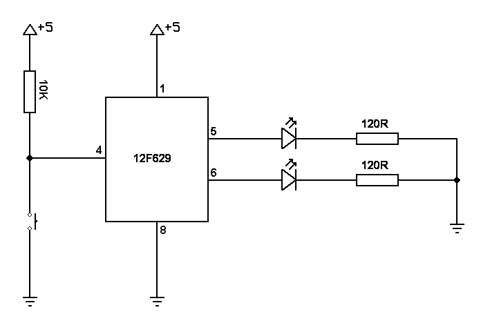
The switch toggles which of the LED pair is the flashing LED.
Three of the six I/O pins are used, 1 (GP3) for input and 2 (GP1 and GP2) for output. The other three I/O pins are pulled up internally. The same principle is used to flash each LED as for the Flash Single LED project above.
The input pin is kept at logic High until the switch is activated which pulls the input pin to logic Low. The PIC program detects when the pin is at logic Low and does 2 things. First it switches to the other LED to flash and second, it waits for the input pin to be at logic High before acting on a logic Low on the input pin again.
The circuit diagram for this is:
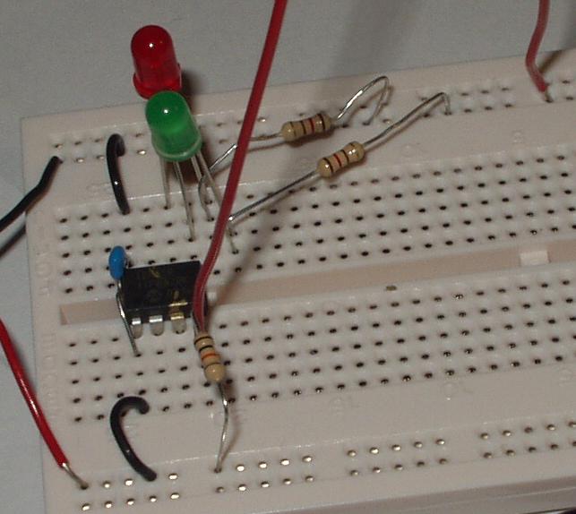
The breadboard looked like this:
The additional µController instructions used in this project are:
| Instruction | Description |
|---|---|
| BTFSC | Skip the next instruction if the specified bit of the specified file register is clear. |
| BTFSS | Skip the next instruction if the specified bit of the specified file register is set. |
The principles used in the Flash Single LED project above are used to flash the selected LED.
There are 2 additions to the project. The first is a file register is used to select which LED is being flashed, and the second is the code that interprets a button press after de-bouncing.
Download the source code and a compiled hex file. See the video. Back to top of page.
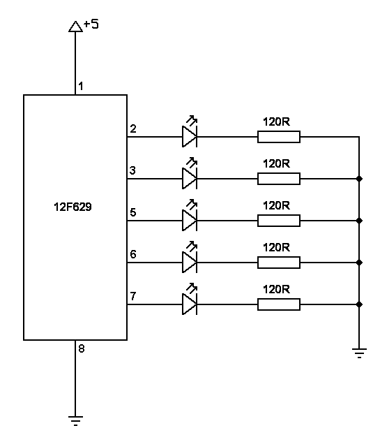
Unlike the Flash Single LED project above which uses programmatic counting, the timer 0 interrupt is used for the delay instead.
Five I/O pin are used. The other pin is input only, and like the Flash Single LED project it is allowed to float.
The circuit diagram for this is:
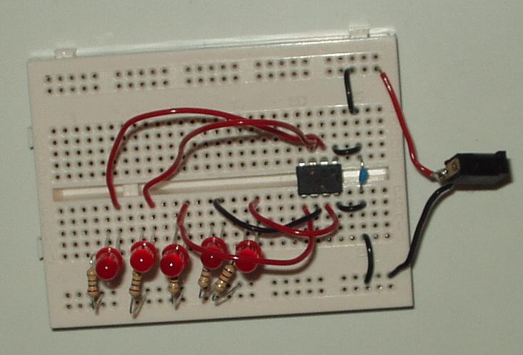
The breadboard looked like this:
The additional µController instructions used in this project are:
| Instruction | Description |
|---|---|
| CALL | Push the position in the sequence of instructions onto the stack and changes the position to the called value. |
| RETURN | Pop the stack restoring the position in the sequence of instructions to the position immediately after the CALL. |
| RETLW | Put the specified byte value into the W register and then do the same as RETURN. |
There a 2 main parts to the program for this.
The first is the way the patterns used to select the LEDs to light are stored and determined. A file register is used to indicate which LED pattern to use. This is used to look up the pattern on a programmed table.
The second is the use of the interrupt generated using Timer0 for determining the delay.
Download the source code and a compiled hex file. See the video. Back to top of page.
This is an advance of the Flash Sequence 5 LEDs. The button selects the direction of the pattern. The input interrupt is used to detect the button push, and timer 0 interrupt is used to debounce the switch as well as for determing delays.
All six I/O pins are used; 5for output and.
The circuit diagram for this is:

The breadboard looked like this:
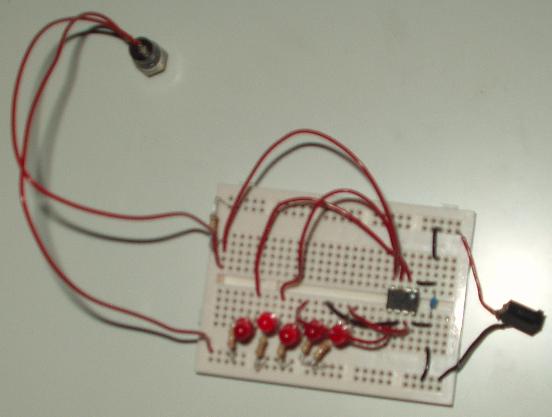
There are 2 additions to this project. The first is to maintain the increment/decrement of the position in the LED patteren. The second is to switch from incremnent to decrement and vice-vera using the TMR0 interrupt to debounce the switch.
Download the source code and a compiled hex file. See the video. Back to top of page.
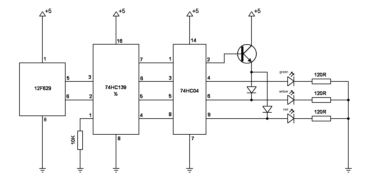
A simple 3 LED traffic light sequencer. The timer 0 interrupt is used for determing delays.
Two I/O pin are used, all for output. The others are pulled up internally.
The proposed circuit diagram for this is:
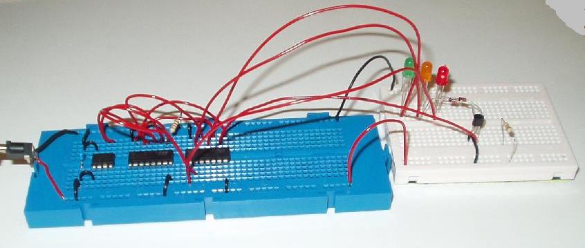
The breadboard looked like this:
Download the source code and a compiled hex file. See the video. Back to top of page.
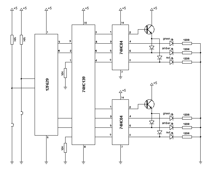
Dual switch dual light-set traffic lights. Each switch makes the request for the respective set of lights to 'go green'. The timer 0 interrupt is used for determing delays. Each 'route' has equal priority.
Four pins are used for output and 2 pins are used for input.
The proposed circuit diagram for this is:
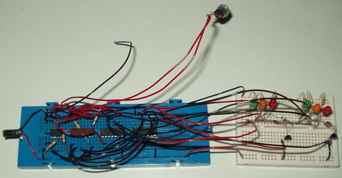
The breadboard looked like this:
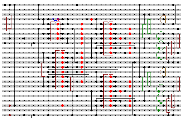
The project is assembled onto stripboard. The layout for it is:
The final assembled Traffic Light Junction Simulator looks like:
Download the source code and a compiled hex file. See the video. Back to top of page.
The A/D converter of the 12F675 is used in this project, which is not available with the 12F629. The other projects can use either the 12F629 or 12F675.
The 8 LEDs are lit depending on the resistance specified by the potentiometer. A 3-8 demultiplexer is used to decode the output from the PIC to the LED driver circuits. Maximum resistance will light all the LEDs, and minimum will light only one.
The proposed circuit diagram for this is:

The breadboard looked like this:
The Analog-to-Digital Converter (ADC) of the 12F675 is used with the resistance of the potentiometer. The 3 outputs lines reflect the octal value computed by the PIC for the ADC.
The output from the 74LS138 is such that the output line is High unless it is the decoded line which is Low. These are inverted using the 74HC04 hex inverter. This inverts only 6 of the lines so an RTL inverter is used to invert the 7th
Why so many diodes? Each time a diode is crossed there is a voltage drop. To maintain equal voltage drop, every electrical route has only one diode, excluding the LED. So every LED gets the same voltage, regardless of how many LEDs are illuminated.
Download the source code and a compiled hex file. See the video. Back to top of page.
All these projects have contributed to the knowledge needed to develop the RS485 Network.