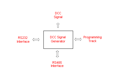
The basic block diagram of the system.

The DCC Signal Generator is supplied with 15V unregulated power which is regulated internally to 12V DC and 5V DC. It exposes 4 interfaces.
More detailed requirements are being defined, and there is a PIC DCC Block Diagram of the DCC Signal Generator itself.
The DCC Signal interface is a continuous low power ±5V output only bit stream and is intended for DCC Boosters.
The Programming Track interface is the ±12V power stream for the programming track. The interface is bi-directional to enable it to detect the DCC ACK from decoders.
The RS-232 Interface is used by the DCC Signal Generator to communicate with the controlling host PC. Commands are sent by the host PC to control the DCC Signal Generator and the other interfaces.
The RS-485 Interface is used to communicate on the Layout Control Bus. The DCC Signal Generator acts as a 'stepping stone' with the host PC.