Back to Tutorials
 
Cone
 

Step 1(Creating the Cone)

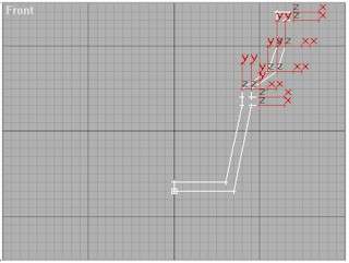
From Create Panel choose Shapes and click on Line then draw the following shape on the Front view port.

Rename the shape from Line01 to Cone

Step 2

Go to the Modify Panel choose Edit Spline then go back to the Cone and select only the vertex selected on the Pic02 then right click on the selection and choose from the popup menu Smooth. Now Click on the Sub-Object button in yellow to Close the Edit Spline Modifier.

Step 3
Click on the Zoom Extents All to center the shape.

Select the Cone, then In the Modify Panel Click on Lathe...

Step 4
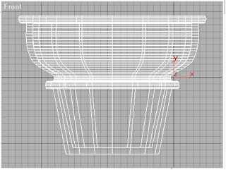
In the Lathe parameters rollout Adjust the segments to 21 and the Align to Minimum by clicking on the Min button. Click again on the Zoom Extents All to center the Cone.
Step 5
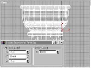
Select the Select and Uniform Scale then right click on it to display the Scale Transform Type-in.

Enter X: 65 and Z: 65 to resize the Cone.


Step 6 (Creating the Material)

Open the Material Editor and select the Material #1 click on Diffuse and enter the following RGB: R:255 G:230, B:180. then click on Ambient and enter the following RGB: R:125, G:115, B:115.

Step 7

Now we have to enter a map to give the material a more realistic look.

Open the Maps rollout and click on the None button which faces the Bump, the Materials/Map Browser opens. Choose Bitmap and click Ok. Then click on the bitmap button and select the cone1.jpg, which will be some where in your hard drive if you download it from this site.

Download the cone bump map

Step 8
  1. Enter a -100 Bump Amount.
  2. Now assign the Material to the Cone by selecting the Cone and dragging the material to it. Or click on the Assign Material to Selection.

Step 9
Select the Cone if it's not selected and go to the Modify Panel and click on UVW Map and select the Option Button Planar in the UVW Mapping Parameters. Now render.


Step 10 (Final)
This is the Final rendering on the Perspective viewport.