|
|
Tools for Testing
Engine
Cases for Cracks at
Oil Cooler Pad

May 2006 ~ Indianapolis, Indiana
Mike Robbins ~ Tech Article #2
| Home |
Tech Pages |
356 Registry |
| Materials Required: | |||
| 1. |
Surplus 3rd piece of engine case. Can be damaged except for lower left corner. Require piston, copper seal and threaded plug for relief valve. Spring not needed. | 6. | Seal for oil cooler |
| 2. |
Block of metal approx 2" x 4" x ½". Soft metal preferred as easy to work with. | 7. | M6 wave washers and nuts |
| 3. |
Pressure gauge with 1/8"NPT male thread...0-at least 150psi | 8. | M8 x 35mm or longer bolt, flat washer |
| 4. | Schrader valve w/ 1/8" NPT | 9. |
2 seals for 3rd. piece to case. |
| 5. | Wood dowel rod ½" x 2" | 10. |
3 M8 wave washers and nuts |
|
|
|||
|
Note:
Dimensions of hole spacing are not included. You’ll have to
determine those from actual parts.
[Saves me the time of
making
drawings] MR
|
|||
 |
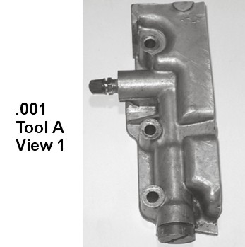
Tool A View 1
|
||||||||
|
|
|||||||||
 |
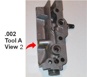
Tool A View 2
|
||||||||
 |
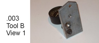
Tool B
View 1
|
||||||||
 |
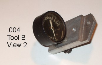
Tool B View 2
|
||||||||
|
Procedure:
|
|||||||||
| Note: These tools and procedure
will only test for leaks on the inlet side of the oil cooler. In >40 years of fiddling with 356s, I have never seen a case leak at the discharge side of the cooler. |
|||||||||
Top