| |

|
 |

Preparation to deliver
and
System in MoscowNew
Story
 Cosmonaut Training
Facility New Photos Cosmonaut Training
Facility New Photos
|
| SSTV
Project Team |
SSTV
System: March 30, 1998
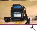
Here is a new picture of the SSTV system.
1. Left, Remote IR control.
2. Right, Apple computers TV camera
3. Center, TASCO SSTV system, with LCD screen.
4. Above center, Kewnood TM-V7A dual band
tranciever
5. Top, Auto Controller, which will automatically
select and send new images.
|
 |
SSTV
during simulated Doppler tests: March 11, 1998
The team has
been testing the proposed SSTV system to see how
Doppler will affect picture quality. The first
series of tests were run at a High power levels
at the receiver, approximately S9.
The FM capture effects help compensate for the
effects of Doppler error.
The initial test results indicates, that stations
with good RX antenna systems will be able to
decode FM SSTV, without having to compensate for
Doppler.
Low power testing will be done at a later date.
On the two meter band, the Doppler frequency
error can be as high as +/- 4kc.
The images attached do not show any distortion of
the image until the frequency error exceeds 5k.
SYS-TEST
SSTV SYSTEM: March 4, 1998
Here are two images taken by new
Apple Camera
 This is an Image of
the video and power cable for the camera.
The image was made using the new Apple
Video camera, which will be used on the
SSTV project.
|

For everyones update on our
progress, here is a picture that I
received from Don, W9NTP this morning,
March 4, 1998. It was sent from Don's
Docking Station (Mir/SSTV Sys) to my
Docking station. ( Down in the right
bottom corner you can just see a part of
Don's Dock Stn that sent the pix.)
This picture should be very typical
of one that could be sent from Earth to
one of the Cosmonauts/Astronauts, also
typical of a picture that could be sent
by one of the occupants aboard Mir to us
here on Earth!
Format
was Robot 36 ( took 36 sec to send)Farrell
Winder, W8ZCF
|
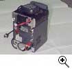
The Kenwood
corporation has delivered 4 Kenwood VM-7A dual
band radio to the Mirex integration facility in
Waldron, Indiana. The Kenwoods are attached to
the TASCO SSTV system.
NEWS:
Feb. 6, 1998
SSTV
PROJECT IS BEING REVIEWED FOR POSSIBLE MISSION.
THE NEXT CREW IS INTERESTED IN BEING ABLE TO SEND
AND SEE IMAGES FROM EARTH.
WE ARE ADJUSTING THE DELIVER SCHEDULES TO DELIVER
ADDITIONAL DOCUMENTATION FOR THE PROJECT TO RKK
BY THE END FOR FEBRUARY.
THERE IS STILL A LOT OF PLANNING TO BE COMPLETED,
INCLUDING:
DELIVERY OF FLIGHT READY HARDWARE
MOUNTING LOCATION
POWER SOURCE
ANTENNA
RADIO BAND
FREQUENCY
|
| |
This is an entry level
Slow Scan Television system designed to be used on board
the Space Station Mir. The SSTV system chosen will
support multiple common SSTV transmission modes.
Specifically designed to be accessible to as many
stations as possible around the world.
Simplicity:
SSTV is a very common mode of image transmutation used HF
and VHF frequencies. SSTV has already been used through
several Amateur Radio satellites, including the Space
Shuttle.
The FM transmission mode, will help reduce interference
and will allow easier Doppler frequency tracking.
| Contents |
|
| 1 |
The
MIR / SSTV Package |
Go! |
| 2 |
Specifications
for Package |
Go! |
| 3 |
Suggested
Transceiver |
Go! |
| 4 |
Video
Operating Mode |
Go! |
| 5 |
Instruction
Plate |
Go! |
| 6 |
Project
Duration |
Go! |
| 7 |
Skill
Level |
Go! |
NOTE:
This specification describes a
simple system that can easily be used as a DUAL
PURPOSE System for SENDING as well as RECEIVING
Pictures To and From Russia, for example.
The Transceiver can also serve as a backup VOICE
Channel.
|
Details:
1. The MIR / SSTV Package consists of:
A
) TASCO ELECTRONIC CO. PARTS:
a) TSC-70 Color Scanner
b) LCD Display
c) Radio Box MR-70
d) Remote Control WR-70 (requires 2 AAA 1.5v alkaline
batteries)
Items a, b, and c are enclosed within a single box with a
small brush-less "muffin" type fan.
B
) TRANSCEIVER:
a) A Kenwood TM-V7 transceiver is mounted on top
of (A) above to form the complete package.
C
) CAMERA APPLE COMPUTER Product # M5673LL/A
(light weight, small, with provision for
Velcro mounting on Spacecraft Window or inside
spacecraft).
a) Camera power cord & Video cable consist of
coiled cables (similar to telephone handset cable).
Maximum extension 15 feet.
 Top Top
2. Specifications for Package (A, B &
C per above)
Electrical:
1. Power Block -- All wiring within
package is terminated on a Power Block on rear of
package.
2. Power Input: +12v, +1.8/-0v
@ ____ amps max.
3. All current carrying wires within the package
are fused with P/N______(Russian) fuses.
4. Each primary power lead to Package is fused
with P/N ______ Russian fuses.
RED lead is +12v, BLACK lead is Ground.
5. Transceiver Output has a 2 foot length of
Coaxial Cable terminated in an SO 239 Connector.
6. Video Output is NTSC.
Mechanical:
1. Weight of Tasco Parts (per A above)
including muffin fan _____kg.
2. Size of Tasco package including a, b, c above
-- within a box 6x6x6 inches.
3. Transceiver (per B above) ________kg.
Environmental:
1. Humidity: 98% RH without
condensation.
2. Temperature operating: 0 degrees to +50
degrees C.
3. Acceleration: All above parts to withstand 8
g's.
 Top Top
3. Suggested
Transceiver:
| Kenwood
TM-V7 |
| Frequency Range |
144
Mhz: |
TX:
144 - 148 Mhz
RX: 118 - 174 Mhz |
| 440 Mhz: |
TX: 430 - 450 Mhz
RX: 410 - 470 Mhz |
| Mode |
F3E (FM), A3E (AM) (VHF Main band Rx
only) |
| Power
Requirement |
13.8 V DC +/- 15 %, negative ground |
Current Drain (High Power)
Transmit |
144 Mhz: Less than 11 A
440 Mhz: Less than 10 A |
| Receive |
144/440 Mhz: Less than 1 A |
| Operating
Temperature |
-4 deg F ~ +142 deg F (-20 deg C ~
+60 deg C) |
| Antenna
Impedance |
50 Ohms |
| Microphone
Impedance |
600 Ohms |
| Frequency
Tolerance |
+/- 3 ppm (14 degF - 122 degF) |
| Weight |
1.2 kg |
| Dimensions,
projections not included (W x H x D) |
5-1/2 x 1-9/16 x 7-7/16 ins |
| |
|
| TRANMITTER |
| RF
Output Power |
HI
Mid (approx)
Low (approx) |
144 Mhz: 50W, 440
Mhz: 35W
10 W
5W |
| Modulation |
Reactance
Modulation |
| Maximum Frequency
Deviation |
Less
than +/- 5 kHz |
| Spurious
Radiation |
Less
than -60 db |
| Modulation
Distortion |
Less
than 3% (300-3000 kHz) |
| |
|
|
| RECEIVER |
| Circuitry |
Double
Conversion Superhetrodyne |
| Intermediate Frequency |
1st IF |
144 Mhz: 38.85
Mhz
440 Mhz: 45.05 Mhz |
| 2nd IF |
144 Mhz: 450 Khz
440 Mhz: 455 Khz |
| Sensitivity
(12db SINAD) |
144
Mhz: Less than 0.16 uV
440 Mhz: Less than 0.16 uV |
| Sensitivity |
-6 db
More than 12 kHz
-60db Less than 28 kHz |
| Squelch
Sensitivity |
144
Mhz: Less than 0.1 uV
440 Mhz: Less than 0.1 uV |
| Audio Output
Power |
More
than 2 W (8Ohms, 5% distortion) |
 Top Top
4. Video Operating Mode
a)
Picture is "grabbed" from camera by pressing
"ACQ" button on Tasco WR-70 Remote Control
Unit.
b) The PRIMARY Operating Mode of this
System is Robot 36. After acquiring a picture, as will be
noted on the LCD Screen, press "36", as noted
under MODE. The TX button is then pressed.
This provides for a repeating cycle of 2 Robot 36
pictures which has a timing of 36 seconds on the 1st
picture, a 20 second interval, then another (repeated) 36
second picture.
c) Picture will repeat per (b) above
until a new picture is acquired.
d) Interval between pictures may be
changed manually by turning system OFF then back to ON as
desired.
e) Picture transmission may be deleted
at any time by turning System OFF or by pressing the RX
button on the remote unit.
Depending on the specification of the Camera, it is
planned that each picture transmitted from Mir will have
a R0MIR ID imbedded in the picture.
Also being considered is a CW ID with the call R0MIR to
be sent between pictures.
 Top Top
5. Instruction Plate
Operating Instructions in both Russian and English will
be attached under a "see through" cover to the
outside of the package.
 Top Top
6. Project Duration
If this project is approved, the SSTV system could be
installed in late 1998.
The system could then run continously until the Russian
Space Station is retireed.
 Top Top
7. Skill Level
This project has
been designed for the more advanced users who can afford
the additional expense of receiving a 70cm signal. The
SSTV format chosen, is one of the simplest formats to be
decoded. We expect a large number of stations to be
tuning in to the down link channel to decode the
continuos feed of Still images.
The frequency and Band have not been chosen at this
time. The SSTV system can operate on any ITU
Satellite frequency in the 2-meter and 70-centemeter
bands.
 Top Top
|