During the winter of 2000/2001 the MacArthur LOCK underwent major repairs. Luckily I was able to obtain a number of on site digital pix of the repair work. These were taken by Charles McCready, III of the Soo.
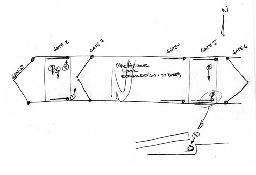
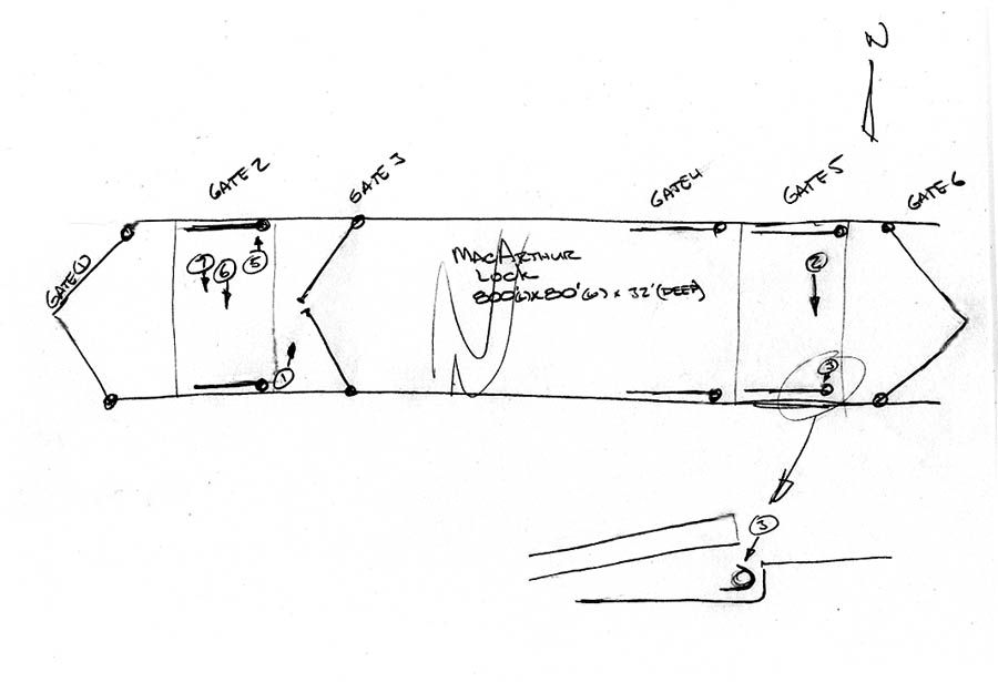
In order to make the pictures more understandable to viewers, Chuck supplied a pencil sketch which shows where he actually stood when snapping the various photos. I have printed the sketch in two magnifications. The smaller one gives an overall idea of what the sketch shows. The larger version is more easily read, but it will require some scrolling in order for you to examine particular areas.

The Soo Locks run in an east-west direction. Consequently, the top of the sketch points to the north. Gate 1 is at the west end toward Lake Superior. Gate 6 is at the right and opens out into the St. Marys River which heads toward Lake Huron. The MacArthur Lock is the closest of the four locks to the Michigan shore line and so the bottom of the sketch is, for all practical purposes, dry land. The Lock is 800 feet long, 80 feet wide and 32 feet deep. It is normally used to handle the older, shorter vessels since it isn't large enough for the 1000 foot long, hundred foot wide giants that are fast becoming the mainstay of the Great Lakes fleet.
Three tents were erected to keep the areas under repair at a temperature of about 65 degrees. Special natural gas lines were run from the main street to the work areas and huge gas furnaces warmed the enclosed spaces 24 hours a day. Due to the short off-season, while the Locks were closed for the winter, the repair work had to proceed at full speed.
Gate 1 remained closed, to hold back the waters of Lake Superior. Gate 6 was closed to keep out the water in the St. Marys River. Heavy plastic tents were built over gates 2 and 5 where major repairs were needed. Another tent, about 200 feet in length was moved along the lock while repairs were made to the cement walls which, after more than 50 years of use, were becoming a bit punky and needed a certain amount of refinishing with fresh concrete.
In Picture No. 1 we see a worker entering the gap at partially open Gate 3 as he heads toward the tented area where cement work is taking place along the lock walls. The snow visible in the picture proves that this is NOT one of the heated locations!
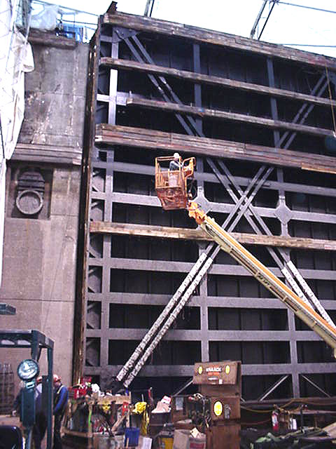
Illustration No. 2 shows the south leaf of Gate 5 which has had its upper hinge pin removed. The leaf itself, has been jacked up from the pintle on which it normally rests and has been moved toward the south wall of the Lock where it is supported on timber cribbing. A man lift carries a worker part way up the face of the 57 foot high leaf.
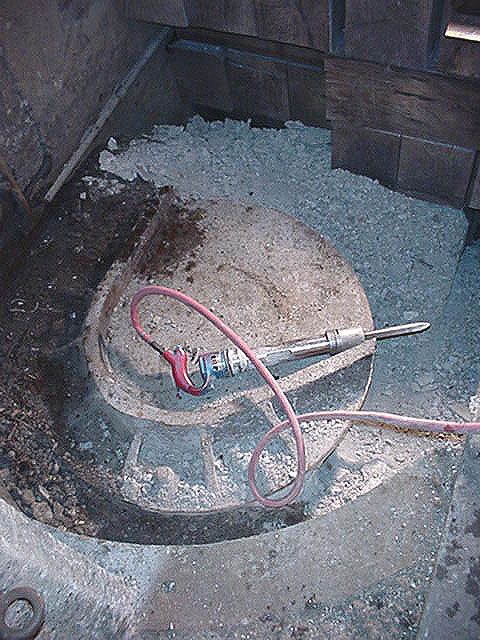
Here, in No. 3 you can see a jack hammer which is being used to remove the old pintle base for gate 5's south leaf. A pintle is a large round steel ball, much like half of a giant roller bearing. You'll see a new one in the next illustration. Although the top of the lock leaf it held in place with a hinge pin, much like you'd use on a door in your home, the base of the leaf rests on a pintle which is NOT firmly set in place. You can see that the pintle base is somewhat U shaped. Normally the pintle supports the leaf in the corner of the U, but if some object such as a chunk of debris or a log floats down through the lock, the pintle will move enough to allow the unwanted item to break loose and not jam or bend the leaf which might happen if it were held firmly in place with a hinge pin at its base.
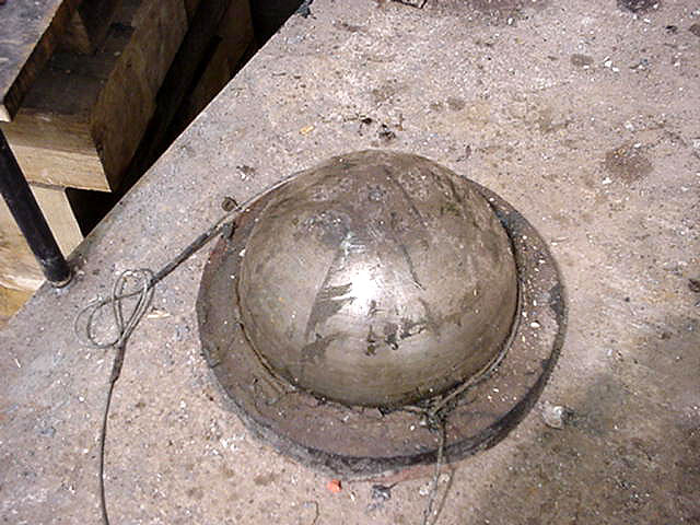
Here, in No. 4, is a brand new pintle waiting to be installed.
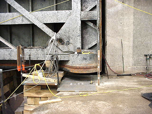
Figure No. 5 shows the old pintle socket of the north leaf of Gate 2. The socket is the round object against which a workman's level is leaning. This socket was cut out with a welding torch and was replaced with a new socket that is bolted into place so that if another pintle socket ever has to be installed sometime in the future, it will be much easier to replace than the original one. At the left, you can see some of the wood timbers used to temporarily support the leaf while repairs are being made.
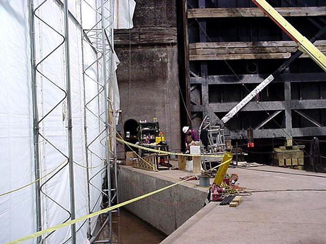
Figure No. 6 shows several interesting items. At the left is the heavy plastic material from which the tents were constructed. In the center of the photo is the bottom of the lock. At the right is the 15 foot wide V-shaped sill which rises several feet above the bottom of the lock. All ships passing through the lock must clear this sill which is needed to provide a water tight seal for the bottom of the gate leaves when the gates close. The temporary timber supports are also visible in the background beneath the south leaf of Gate 2.
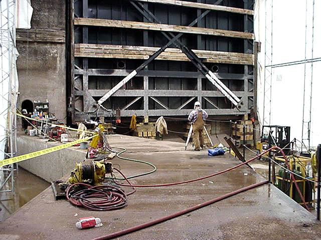
Figure No. 7 gives a somewhat wider angle of view than No. 6. Here you can see both tent walls which keep the work area at around 65 degrees. The bottom of the lock as well as the sill show up very well, too.
This last photo appeared on The Corps of Engineers Webcam site at the Soo March 25, 2001. At the left, you can see that the tent over Gate 5 is still in place since work on the MacArthur Lock hadn't quite been completed.
A thousand foot freighter can be seen on the right smashing its way through ice in the Poe Lock as it heads upbound toward Lake Superior on its first trip of the season.
Proceed to the next page to view THE MILWAUKEE CLIPPER as photographed on April 6, 1998.
Or you may Return To My Home Page.