| Have
been modelling NZR since 1994, this is my second layout, this one being
brought on by moving house. The layout is in a 12 x 6 mtr room; the
layout itself measures 9 x 4 mtrs. It consists of 2 main lines with
half of 1 main line hidden to give a section showing a single main.
Total track laid is 90mtrs + Basic Description; Track - HO code 100 combination of Peco, GT rail and Atlas with Kenzy Plastics NZR sleepers, Points - Mainly Peco Electrofrog with a couple of Insulfrogs and Shinohara’s. These powered by Peco solenoids and Tortoise motors. Power/Control – Is by Digitrax, a DSC 100 comand station, controllers being a DT400 and 2 x UT4. Also 1 x PM 42 for track section and reverse section control. Framing – Wood girder construction with bearers every 300mm Track bed – Station areas are on Pinex soft board, main line areas on 7mm ply, all track is laid on 1mm ‘Inseal’ builder’s rubber. Scenery – construction of scenery is with 10 x 50mm 2400x 1200 styrene sheets cut to shape and glued with Selley’s ‘No more nails” sculpted and painted with acrylic Resene paints. Concept – Typical NZR operation and scenery of the 50’s and 60’s in NZ. There are 4 different station profiles of no particular place with the exception of Carterton. Carterton has a unique track formation and buildings, this I have modelled as it was in 1965. The other 3 station profiles follow no particular area but have different classes of station and facilities / buildings and offer the modeller and the operator both challenging and operational skills. For instance a nice landing /wharf area has been modelled for rail/boat traffic in one area, logging in the other and a phosphate plant further round. Whilst the main station profile (yet to be formed) will house all the facilities and yards. Rolling Stock and Motive power – Have over 130 wagons (4 wheel and bogie type), 5 steam, 9 diesels, 1 railcar, Landrover weed-sprayer and a 40ton Craven crane. All rolling stock is pre 1970. Buildings – All are scratch built from either plans or photographs and painted accordingly. |
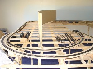 After the main frame, construction of the track bed and risers |
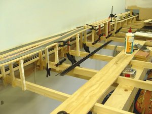 Positioning of the risers for elevated track |
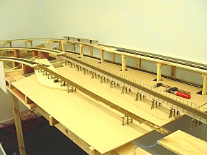 Initial planning and position of bridges |
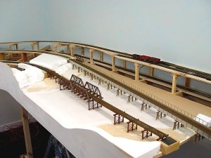 Construction of the riverbanks with styrene |
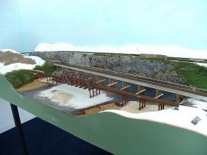 Scenery of the riverbank and creation of the rock face (plaster and tin foil) to the back scene |
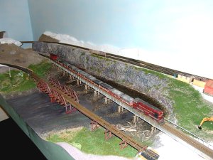 Forming of the riverbed (Woodlands scenic water) and adding the small detail |
‘Inseal’ is laid down then the track follows |
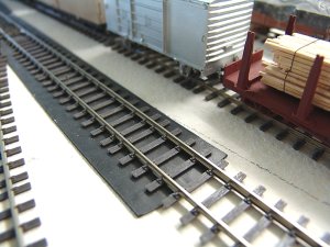 Closer detail of the Kensey sleepers and ‘Inseal’ tape |
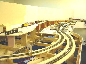 Track laid in the station area and risers |
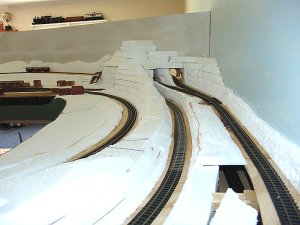 Styrene is roughly cut to shape and glued (No more nails) in place |
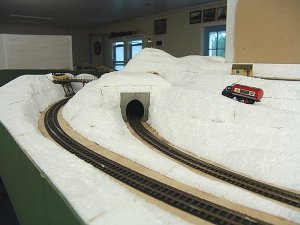 Styrene is now formed to shape by using a rasp and rough sandpaper |
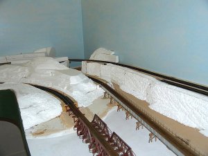 Styrene cutting and forming of the hills and banks |
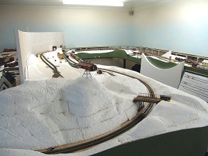 Styrene now ready for painting |
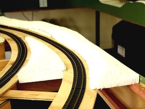 Shaping and gluing the styrene between the risers |
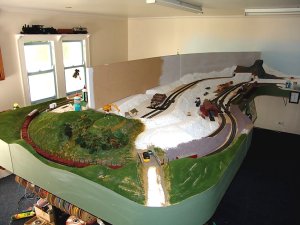 After forming the styrene, ground is then painted (Resene test pots) and ground form added prior to adding the detail foliage |
Detail foliage and such added. |