

My present invention relates to closures for receptacles and more particularly to stoppers for bottles, and it has for its object to provide a simple, inexpensive and convenient stopper of a self-closing nature through which liquid contents can be poured without removal of the stopper though such contents are sealed and protected when the bottle is maintained in an erect position. To these and other ends, the invention resides in certain improvements and combinations of parts, all as will be hereinafter more fully described, the novel features being pointed out in the claim at the end of this specification.
In the drawing:
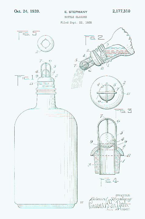
Fig. 1 is an elevation of a bottle, jug or flask fitted with a stopper constructed in accordance with and illustrating one embodiment of my invention;
Fig. 2 is a fragmentary view thereof, partly broken away, illustrating the behavior of the stopper valve during the operation of pouring;
Fig. 3 is an enlarged top plan view of the stopper;
Fig. 4 is a vertical central sectional view on the scale of Fig. 3, and
Fig. 5 is a top plan view of the stopper cap.
Similar reference numerals throughout the several views indicate the same parts.
My invention is to be distinguished from the so-called ball type non-refillable bottles in that resistance to refilling is not its purpose or function. On the other hand, my stopper simply replaces the solid cork cap or other original closure and is particularly useful at beverage bars for facilitating the pouring of beverages without removing the stopper and protecting the liquid against insects and other foreign matter, as well as evaporation.
Referring more particularly to the drawing, 1 indicates a body portion of cork or similar material having the usual exterior form and taper of the ordinary bottle cork. It is surmounted by a cap 2 that is preferably of hard or unyielding material of an inexpensive nature, such as one of the commercially common synthetic products of condensation, or it may be of metal. Extending centrally through both elements is a preferably metallic tube 3 that projects above the cap to constitute a pouring mouth and also a valve seat 4. A gravitational ball 5 of china or glass normally closes this seat and hence seals the bottle when the latter is in erect position, as shown in all figures except Fig. 2.
Surmounting the cap and enclosing and confining the ball valve 5 is a cage 6 constituted by two or more crossed wickets or wire loops. These are soldered together at their point of intersection 7 and their lower ends are anchored in the stopper or cap. The cage preferably fits the ball quite closely or vice versa so that the latter rolls freely in it as on a track when the bottle is tilted but easily and inevitably rolls into the valve seat 4 as soon as the slightest upward angle is given to the structure. Thus, as shown in Fig. 2, the ball rolls to the end of the cage during the pouring operation allowing plenty of room between it and its seat for the liquid to be dispensed in a stream of satisfactory and not too great volume, as indicated in Fig. 2. Also, the projected ball valve is in a position to slow the rush of the contents and to cause it to drop naturally into the glass or other receptacle.
At this point, it is to be noted that I make the cap 2 of greater diameter than the neck of the bottle or at least greater than that of the natural mouth thereof so that its perimeter overhangs as at 8 and constitutes a drip shed so that the liquid will not work in between the cap and bottle mouth and will not streak or soil the exterior of the bottle as the latter is placed upright after pouring.
The lower ends of the cage wires 6 may be anchored in the cap 2 or secured to the tube 3 or both. If the wires and tube are of metal, I prefer to solder them together at 9, but if the cap is also of metal, I prefer to solder all three together at substantially the same point.
As before stated, my closure or stopper is compact, light, inexpensive and subject to instant application to a bottle mouth once its original seal is removed and at a beverage bar at which a number of individual drinks are served from the same bottle, much time is saved the bartender in capping and uncapping the bottle while the device is also a corresponding convenience to the customer. It is also adapted for private use in the home.
I claim as my invention:
In a bottle closure or the like, the combination with a stopper for the mouth of the bottle embodying a body portion having a tube extending centrally therethrough with a projecting end terminating in a seat on the exterior, and an overhanging liquid-shedding cap surrounding the projecting end of the tube, of a cage rising above the seat and constituted by a pair of crossed wires having their lower ends extending down the exterior of the tube in to the cap and soldered to the tube within the cap, and a ball valve confined within the cage to traverse the same and adapted to normally occupy and seal the seat, the assembly being so compact that the ball when in the seat is also partially within the cap.
EDWARD STEPHANY.

Editor's Note: Many thanks to my 2nd cousin Rosemary Miller for providing me with this information about my great-grandfather.

