Super-detailing the Airfix Mark I Tank
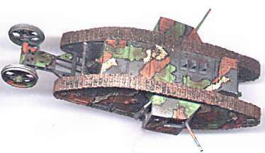
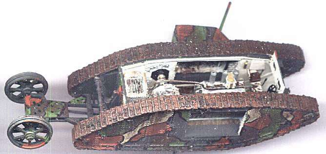
The Airfix Mark I Tank was released in 1967 costing 2s 3d. It is
to 1/76 scale, not 1/72 as claimed on the current box artwork. Neither is it,
strictly speaking, a Mark I, but rather, a hybrid: a Mark II with tail wheels.
Back in 1967, there was no Mark I at the Tank Museum, Bovington. The current
vehicle displayed arrived from Hatfield Park in 1969, so Airfix appear to have
based their model on the very similar Mark II that was on display. The end
result is dimensionally accurate, but needs some minor modifications to make it
a true Mark I. In particular, the cab needs widening, the angled roof hatch
needs removing, and a circular hatch installed.
When I decided to build a Mark I male, I thought it would be
interesting to perform an even more complete job than just the above two
corrections. I see lots of super-detailing work being performed in 1/35 scale,
so why not 1/76? This is the account of that project, which took a considerable
time, mainly working for short periods on odd evenings after work, and which
also took quite a lot of research in and around the vehicles at Bovington. In
places I have gone for appearance rather than strict accuracy, but I hope the
end result is acceptably accurate.
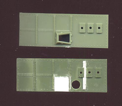
Let's first look at the roof detail.
I removed the original oblong angled hatch assembly and blanked it off with
plastic card. A new aperture for the circular hatch characteristic of the Mark I
was drilled. You can see the before and after layouts in the picture. Note that
a raised lip with rivet detail has been added between the rearmost two exhaust
ports. The exhaust piping provided in the kit is not correct for a Mk I, so this
will need replacing with roof-shaped "hats" over each exhaust port.
Next, the driver's and the commander's visors
need modifying. I opted for having them opening, with some loss in accuracy due
to the minuteness of the hinges, but anyway, the Airfix visors are not strictly
correct in that the covers for the slitted visors do not themselves have
vision slits. The apertures behind the visors are plain oblong openings, with
rounded corners. The driver's cab on the Mark I is wider than that on the Mark II, so I
have cut off the original outer hinge brackets and added another set cut from
a spare front plate. These show up as darker green in the picture. The
method of making the hinges
for the visors is given separately. As can be seen, I cut the
visor plate from the glacis plate. This was for ease of handling - it is easier
to work on a flat plate than two plates joined at an angle. This plate was also
thinned down with a file, until the slits in the
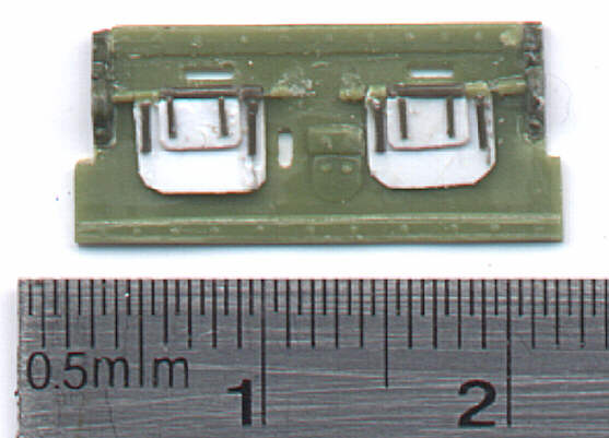
plate were exposed. You can see the white background
showing through these in the picture. On the inside of these are replaceable
vision blocks with their mountings. Other inside details for this plate include
the mounting plate for the commander's machine gun, and the levers for adjusting
the visors. A good idea of their appearance can be obtained from
Look Inside
Cross Sections: Tanks. Having made a wider cab front, it is then
necessary to make a new cab to fit in place of the original Airfix part. I
fabricated this from 10 thou plastic card. Embossed rivet detail was added on
strips of plastic card.
A word on embossing rivets is appropriate here: I found an old metal gear wheel from a
friction motor. This had teeth at the right pitch for my rivets, so I mounted it
in the handle of a discarded toothbrush to provide me with a suitable
marking-out tool

which could be run along the edge of a metal rule to provide a straight line of
rivet marks. The shape of the gear teeth meant that these marks were not in
themselves suitable as rivets, but they provided locations for final
embossing using a blunt pin. This I prepared by filing the tip of a pin flat (a
pointed tip will tend to perforate the plastic card) and then held it in a pin
chuck so that only sufficient of the pin protruded from the chuck as to provide
the required depth of embossing. Embossing was then performed rivet by rivet
using the gear wheel marks as a locating guide. I used a plastic mat under the
card to provide a surface to work on. A hard surface is unsuitable. Lines
of rivets can then be cut from the embossed card using a ruler and scalpel.
These embossed strips were used extensively to add interior rivet detail
throughout the vehicle.
This completes the
essential exterior changes, although some extra detail can benefit the tail
wheel assembly. I suggest a close examination of the vehicle at Bovington, if
you can get a good look despite the full scale diorama it is now displayed in!
There are also good pictures in Trevor Pidgeon's excellent book The Tanks at
Flers
, a book that I cannot recommend
highly enough.
|
Engine assembly
|
|
|
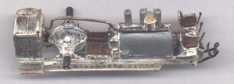
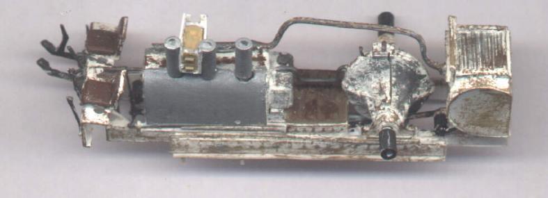
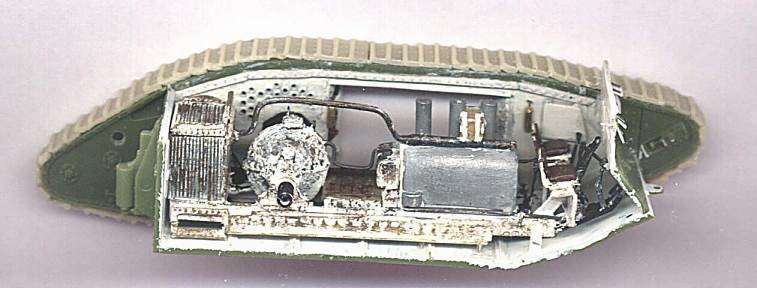
Next, the engine assembly. This dominates the interior
of the vehicle, and is constructed on a sledge-like base. I made the engine with
the covers in place, which makes life a little easier. The interior of the Mk II
is almost identical to the Mk I. There are good pictures in The Tanks at
Flers
of the interior of the Bovington Mk II which I used in conjunction with my own
pictures. Unfortunately, the perspex windows in place on the Bovington Mk II
make effective photography difficult and the photos invariably end up spoilt by
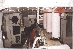
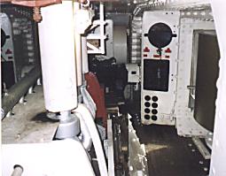
reflective flare. The interior of the Mk IV is easier to photograph and is
very similar.
|
Mk IV Looking aft through visors |
|
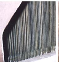
The tubes for the tubular radiator were made from stretched sprue. I had some
difficulty finding out the correct pattern for this radiator, but finally
managed to photograph it through a hole in the side of Bovington's Mk II. The
tubes are evidently copper, and have gone a nice verdigris colour.
The main differential housing was modelled out of filler built up on an appropriately sized wheel from the
scrap box. Pipework for the cooling water circulation was made from brass rod,
suitably bent. The lagged exhaust pipes were made from polystyrene tube.
The driver's and
commander's seats are very simple affairs, with thin padding for the seat and
back. They are mounted on a perforated cross-beam, that in turn is placed on
brackets on the front of the engine sledge. The cross beam is full width of the
hull interior and also provides mounting points for the control levers. Again,
The Tanks at Flers is a good source of information for this and for details of the various controls. Behind the
driver is an hydraulic pump for lifting the rear wheels. This is driven from the
main engine, and controlled by a lever which protrudes forwards and to the left
of the driver. I could only find sketchy details for these items. Further
information would be gratefully received. The driver's steering wheel is mounted
on the interior of the glacis plate. I made the wheel from stretched sprue and
the spokes from 10 thou sheet. To form the stretched sprue, I wrapped the sprue
tightly round a slightly undersized metal rod, secured it with tape, and
immersed it in boiling water. After cooling, a ring can be fashioned from a
single turn of the resulting the sprue coil.
The interior surfaces of the hull sides need
apertures cut for the transmission cross-shaft, and the addition of ammunition
stowage. I inserted pieces of perforated loudspeaker grill into apertures cut
out of the inner hull sides for the shell stowage tube locations. The pitch of
the holes was too large, however, but attempts to drill plastic card to a closer
pitch were not successful, so I settled for general appearance, rather than
strict accuracy. Probably, a better solution would be to use photo-etch
techniques to etch the holes into a brass sheet, and in future I intend to set
myself up to make such photo-etched parts from computer printed masks. I did use
drilled polystyrene sheet for the ammunition stowage in the sponson apertures
and within the sponsons. I printed the marking out pattern by computer onto
paper and pricked it through onto plastic card with a needle to provide punch
marks for hand drilling the holes using a pin-chuck mounted drill. The shells
were 57mm, so in 1/76 scale the holes need to be clearance fit for tubes
of 0.75mm interior diameter, i.e. ~1mm.
Each of the ammunition stowage tubes was made by
rolling aluminium sheet obtained from a Chinese take-away dish (thicker than
kitchen foil) around the shaft of a watchmakers screwdriver. These tubes may be
tapered for ease of insertion by rolling them further on a tapered mandrel - I
used the needle from a springbow compass. The same techniques
were used for shell stowage in the sponsons. In cases where there is
insufficient depth behind the perforations to permit tube insertion it is
necessary to surface mount aluminium rings to represent the stowage tubes. I
secured the tubes in place with office gum as neither superglue nor polystyrene
liquid cement is suitable for bonding aluminium to polystyrene.
In addition to these major items of detailing, the fuel tanks need to be positioned on either side of
the driver and commander (see The Tanks at
Flers), and brass fire extinguishers have to be provided. I made
these from brass rod, which saves a painting problem. The interior of the rear
door, including the latch, needs placing on the back-plate of the vehicle.
Having completed the interior details
for the hull, the engine assembly can be glued in place, together with
duckboarding between the sponson apertures and the engine assembly. The 12V
battery should be placed under the left of the differential assembly.
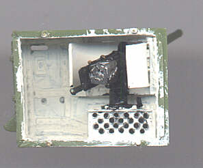
Next, the sponsons. I
first removed all mould marks and other unwanted blemishes from the inner
surfaces. This included the gun mounting locations. I then drilled out the
vision slits and drilled the internal pistol port locations to half the
thickness of the plastic. The machine gun locations need mounting plates. Rivet
detailing strips were added. There is a picture of the interior of a Mk IV
sponson in
A New Excalibur (another fascinating
read) which I used as a guide. Unfortunately, the sponson that was on display on
a transport trolley at Bovington is no longer to be seen. I made new gun
shields from sheet plastic, ensuring the provision of the slots for the gun
sights. These shields were heat formed on a suitable rod in the same manner as
the steering wheel sprue described previously. The sponson doors were thinned
down, and the disposal chutes at the door bottoms were filed to give an opening.
Pistol ports were partially drilled and door latches added.
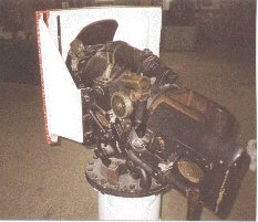
The Hotchkiss 6 pounder guns were fabricated from
scratch, using a couple of heavily modified PaK 40 breech blocks from the bits
box. Details of these guns can be found in Profile Publication's AFV 1914
'19 and A New Excalibur . A short barrelled version as used in
later marks of tank is on display at Bovington, see photo.
The sponsons can be made to be
removable by judicious use of brass pins for fixing them to the hull
sides.
For final finishing, I fitted Matador Models resin tracks in place of the vinyl tracks
supplied with the kit. These have a pleasing irregularity and seem to me to be
more like the originals. They have the advantage that single links may be used
round the horns. For painting, the colour scheme for the Mk I is more
interesting than for later vehicles, with black outlined areas of green,
red-brown and cream camouflage. It is worth noting that only C Battalion
vehicles had grenade nets on the roof, so a D-numbered vehicle may be preferable
on grounds of robustness if the top plate is to be removable to view the
interior. The Tanks at Flers provides a good source of vehicle histories for choosing a specific tank to model. I found that by careful
positioning of the tracks it was possible to make the top plate clip positively
into position which together with a removable cab structure gives adequate
access to the interior.
I have not covered every possible
detail, but hope that this article, together with the bibliography may encourage
others to try this or a similar project in 1/76 scale. Just because it is
smaller does not mean you have to settle for less detail!
Bibliography
The Tanks at Flers, Two Volumes, Trevor Pidgeon.
Fairmile Books, 1995
AFV 1914 '19, Armoured Fighting Vehicles of World War
One. Profile Publications, 1970. Now republished.
A New Excalibur, The Development of the Tank 1909 -
1939, A.J. Smithers. Leo Cooper, 1986.


 Let's first look at the roof detail.
I removed the original oblong angled hatch assembly and blanked it off with
plastic card. A new aperture for the circular hatch characteristic of the Mark I
was drilled. You can see the before and after layouts in the picture. Note that
a raised lip with rivet detail has been added between the rearmost two exhaust
ports. The exhaust piping provided in the kit is not correct for a Mk I, so this
will need replacing with roof-shaped "hats" over each exhaust port.
 plate were exposed. You can see the white background
showing through these in the picture. On the inside of these are replaceable
vision blocks with their mountings. Other inside details for this plate include
the mounting plate for the commander's machine gun, and the levers for adjusting
the visors. A good idea of their appearance can be obtained from Look Inside
Cross Sections: Tanks. Having made a wider cab front, it is then
necessary to make a new cab to fit in place of the original Airfix part. I
fabricated this from 10 thou plastic card. Embossed rivet detail was added on
strips of plastic card.
  which could be run along the edge of a metal rule to provide a straight line of
rivet marks. The shape of the gear teeth meant that these marks were not in
themselves suitable as rivets, but they provided locations for final
embossing using a blunt pin. This I prepared by filing the tip of a pin flat (a
pointed tip will tend to perforate the plastic card) and then held it in a pin
chuck so that only sufficient of the pin protruded from the chuck as to provide
the required depth of embossing. Embossing was then performed rivet by rivet
using the gear wheel marks as a locating guide. I used a plastic mat under the
card to provide a surface to work on. A hard surface is unsuitable. Lines
of rivets can then be cut from the embossed card using a ruler and scalpel.
These embossed strips were used extensively to add interior rivet detail
throughout the vehicle.

 Next, the sponsons. I
first removed all mould marks and other unwanted blemishes from the inner
surfaces. This included the gun mounting locations. I then drilled out the
vision slits and drilled the internal pistol port locations to half the
thickness of the plastic. The machine gun locations need mounting plates. Rivet
detailing strips were added. There is a picture of the interior of a Mk IV
sponson in A New Excalibur (another fascinating
read) which I used as a guide. Unfortunately, the sponson that was on display on
a transport trolley at Bovington is no longer to be seen. I made new gun
shields from sheet plastic, ensuring the provision of the slots for the gun
sights. These shields were heat formed on a suitable rod in the same manner as
the steering wheel sprue described previously. The sponson doors were thinned
down, and the disposal chutes at the door bottoms were filed to give an opening.
Pistol ports were partially drilled and door latches added.