Ultracentrifugal Engine Prototype 1
By Jim Bowery and Roger Gregory
Copyright 2002
The aluminum engine photographed here (which I've nicknamed "Wheelhammer Odeen") weighs about 1lb and is designed to develop about 100lbs thrust. This device was fabricated at a high performance automotive shop under the direction of mechanical engineer, Don Scott, based on the technology and computer models developed by Roger Gregory and Jim Bowery. It is designed for thermal shrink fit rather than welding. The the patent is available online from the US Patent Office's web site. You may also be interested in a brief description of why this technology is important and a nascent frequently asked questions list.
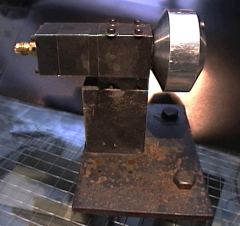
This is a side view corresponding to Figure 1. The brass gas fitting on the left is the LOX inlet. Not visible is the
inlet for LPG on the opposite side. The feed assembly includes two silicon nitride
bearings and a rotary seal. The ultracentrifuge wheel is at the right and exhaust goes out to
the right.
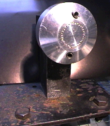
This is an end view corresponding to Figure 3. Two tungsten alloy nozzles are thermal shrink fit into
place at 8 degrees from axial to provide rotational torque that turns the wheel.
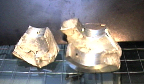
This is an "exploded" view of the wheel resulting from a hard start. The piece on the right
shows the toroidal chamber and two impeller/cooling channel inlets for
propellant. One is for LOX and the other is for LPG.
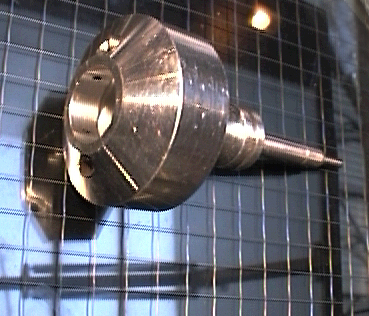
The wheel with the spindle is here decoupled from its thermal shrink fit and pulled out. Two
of the LOX impeller/cooling channel inlets are visible on the inside diameter
of the wheel, as well as the two nozzles.
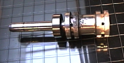
The propellant spindle is here in a side view corresponding to Figure 2. The holes deliver the liquids
to grooves that allow easy mating of the impeller/cooling channel inlets to
the spindle by providing a continuous ring of liquid for the inlets to meet.
This thermal shrink fit is not sensitive to the rotational orientation of the parts; only
axial. A brass tube (not shown) fits down the center of the spindle neck on the left delivering
the LOX to the right-most groove. The LPG is delivered in the cylindrical space
between the brass tube
and the spindle neck to the left-most groove. Both liquids are spun up before
delivery to their respective grooves thereby matching the velocity of the centrifugal
pump inlet.


