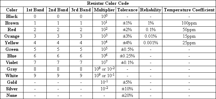
Resistors are coded with a series of colored stripes used to represent the value of the resistor, tolerance, and and sometimes the reliability or temperature coefficient. The above chart is probably the largest you will see, because I tried to include every possible resistor type there is. If you look at a few different books and websites and compare their charts, chances are that they will be different, and may even contradict one another in areas. The chart I have provided is somewhat more confusing than most, but once you understand it you will see that it contains every possible meaning to a code on a resistor, whereas another chart may give the wrong reading to some resistors.
The first two bands on a resistor are always the first two digits of the resistance. The third band contains the third digit, but may not be included in some resistors. After the first two or three digits comes the multiplier. This number represents the power of 10 that is then multiplied with the first digits to give the resistance. Note that a gray or white band used as the multiplier has two possible meanings. The bands usually represent 10^8 and 10^9, but in some oddballs they may actually mean 10^-2 and 10^-1. More often you will see a silver or gold stripe used to represent 10^-2 and 10^-1. The next band, and most often the last, is the tolerance band. This band indicates what the actual value of the resistor may be. The actual resistance of the resistor must be within this percentage of the rated value, or else it is considered no good.
The reliability and temperature coefficient bands are not included on many resistors, and they will never both be on the same resistor. A reliability band indicates the failure rate per 100 hours. The temperature coefficient band specifies the maximum change in resistance with change in temperature, measured in parts per million per degree Centigrade (ppm/°C). You will see reliability bands more often on older resistors, and temperature coefficient bands on newer ones.
If a resistor has four bands total (or three bands if the tolerance is ±20%), it will contain two digits, a multiplier, and a tolerance band. If a resistor has five bands and is a newer one, it most likely has three digits, a multiplier, and a tolerance band. If an older resistor contains five bands, it is probably one containing two digits, a multiplier, tolerance, and reliability band. You will probably only ever see newer resistors with six bands, and they will include three digits, multiplier, tolerance, and temperature coefficient bands.
Lets say you have a resistor with a yellow, violet, red, and gold band. The first band represents the first digit, and a yellow band means 4, so the first digit in the value of the resistor is 4. The next band is violet, meaning 7 is our next digit. The next band is our multiplier, and will tell us to what power of 10 we must multiply the first two digits by. A red band in the multiplier means 10^2, so to get the value of the resistor we must multiply 47 by 10^2. This gives us 4,700 ohms, or 4.7 kiloohms. The last band is the tolerance, a gold band meaning the actual value must be ±5% of the value on the resistor. So the actual value of the resistor may be anywhere from 4,465 ohms to 4,935 ohms. If we were to then measure the resistance of the resistor with a DMM and found that it was <4,465 ohms or >4,935 ohms it would be defective.
Sometimes figuring out what end is what can be difficult. Some resistors will have the bands close to one end, indicating the starting point. On others, the last band will be larger than any of the others. But in many resistors it is common for all stripes to be evenly distributed and equal in width. If you have a gold or silver stripe, the end that stripe is furthest from is your starting point, because we know gold and silver cannot be used for any of the digit values. But sometimes you might have a resistor such as brown, green, black, red, brown. It could be either be read as a 15k ohm ±1% or 12M ohm ±1% resistor. If you are stuck in a situation where you cannot figure out what end is what, the next best thing is to just get a DMM and measure it.
Resistors are manufactured in standard values, known as the E series. The most common series is the E12, where there are 12 resistors in a decade (1.0, 1.2, 1.5, 1.8, 2.2, 2.7, 3.3, 3.9, 4.7, 5.6, 6.8, and 8.2). Other series include the E6, E24, E48, and E96 series. The values in the series are spaced similar to how notes in an instrument are. To get the approximate value of a resistor in one of the series, the equation v=10^((n-1)/E) can be used, where v is the value of the resistor, n is the number of the resistor, and E is the series. For example, say you want the approximate value of the 3rd resistor in the E12 series. The value will be v=10^((3-1)/12)=1.467799268, or 1.5 when you round up the value.