Perf Boards /
Lochrasterplatinen
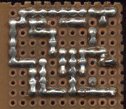
Perf(orated) boards are well
suited to realize prototypes of simple electronic circuits. Many
people believe, that the electrical connections on the bottom side of
the PCB have to be done using small wires or even component wires
bent over. That's a misunderstanding. It is faster and much cleaner
and more friendly to modifications if the connections are made from
solder that is deposited on every solder point on the later way of
the trace and melted together. That is easy to do using a correctly
(lower) temperated soldering iron, and because the solder is much
thicker it is at least as conductive and can carry as much current as
a trace of copper. The components are mounted in the same way as on a
normal PCB. The wires are cutted and not bent over before soldering
them in. This way the components are easily desolderable. Here two
examples enlarged by 2:
Zum Aufbau von Prototypen
einfacher elektronischer Schaltungen eignen sich Lochrasterplatinen
sehr gut. Viele Leute denken, das dabei die elektrischen Verbindungen
auf der Unterseite der Platine mit kleinen Drahtstückchen oder
gar umgebogenen Bauteileanschlüssen herzustellen sind. Das ist
ein Irrtum. Es geht viel schneller und ist viel sauberer und
änderungsfreundlicher, wenn man die Leiterbahnen aus Lötzinn
aufbaut, in dem man auf jedem Lötpunkt auf dem Weg der späteren
Leiterbahn einen Lötklecks setzt, und diese durch Schleppen mit
dem Lötkolben untereinander verbindet. Das geht bei einem auf
richtige (niedrigere) Temperatur eingestellten Lötkolben sehr
einfach und schnell, und das Lötzinn ist bei der Dicke
mindestens so leitfähig und strombelastbar wie eine Leiterbahn
aus Kupfer. Die Bauteile werden wie in einer normalen Platine
durchgesteckt, die Anschlussdrähte abgeschnitten und nicht etwa
umgebogen, und ganz normal unten mit dem Lötpunkt verlötet.
Dadurch sind die Bauteile auch einfach wieder auslötbar. Hier
zwei Beispiele im Massstab 1:2:
|
|
|
|

|
|
|
|
|
|

|
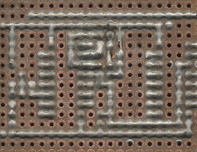
Here we cheated, because the
long supply traces are straigtened out with an enclosed thin wire.
Crossing traces use a jumper wire on the top side, just like on a
regular PCB.
Hier wurde etwas gemogelt, weil
unter den Stromversorgungsleitungen doch dünne Drähte
liegen. Bei sich kreuzenden Leiterbahnen wurde auf der
Bauteileseite ganz sauber eine Drahtbrücke eingesetzt, so wie
bei richtigen Platinen.
|
|
|
|
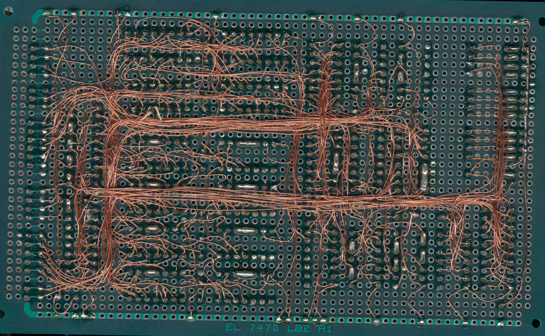
Using enameld copper wire of AWG32
it is possible to construct PCBs on a perf board that are as complex
as multilayer boards. Because the enamel is removed using the
soldering iron at about the same temperature when the copper clad of
the PCB gets off, tin the ends of the wire in a small drop of solder
on the tip of your soldering iron before your fix it onto the pads.
Use sockets for the ICs because removal of the components is nearly
impossible, and because checking for mistakes is difficult.
Bei der Fädeltechnik
verbindet man die Bauteile auf einer Lochrasterplatine mit lötbaren
Kupferlackdraht von 0.2mm Durchmesser. Damit lassen sich Platinen
herstellen, deren Komplexität mehrlagigen Multilayerplatinen
entspricht. Da der Lack vom Kupferlackdraht erst etwa bei der
Temperatur abbrennt, bei dem sich auch die Kupferflächen von der
Platine lösen, verzinnt man den Draht in einem Tropfen Lötzinn
am Lötkolben bevor man ihn festlötet. Aber die eingelöteten
Bauteile sind kaum noch auswechselbar, für ICs sollte man also
Fassungen verwenden, und die Fehlersuche ist schwierig.

(Bild von Tim Böscke,
leider nicht mehr unter TU-Harburg veröffentlicht, aus
web.archive gerettet)
http://www.elexs.de/faedel0.jpg


