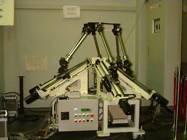

The prototype is a 6 d.o.f parallel manipulator composed of a mobile plate and a fixed base plate, connected by six constant and identical length links which are low-diameter cylindrical bars. The two extremities of each link are articulated respectively with the linear rail fixed on the base plate and with the mobile plate through universal and respectively spherical joints. The linear actuator obtained from the combination of an electric motor and a ball-screw system, enables to move the articular point Ai (i=1,6) along an axis with inclination angle beta=pi/6 which is one of design parameters. By changing the position of these points Ai (i=1,6), the position and orientation of the mobile plate can be controlled with respect to the base plate. This special architecture allows to use light links and to keep the motors, which constitute the havy part of the robot, fixed on the base. Therefore, fast movements can be performed. As the weights of the individual motors do not affect the overall performance of the robot, the direct drive concept is introduced. Each link is driven by a 750[w], 4.4[A] AC servo motor (Yaskawa) giving 2.39[Nm] nominal and 7.1[Nm] peak torques through a transmission consisting of a rack and ball screw system. An incremental rotary encoder with a resolution of 2048 pulses per revolution is connected directly to each motor to measure the linear displacement of the link. With the ball screw transmission, the resolution of the encoder is 51.2 pulses per mm. In addition, two rotary potentiometers are mounted on the gimbal axes at the lower end of each of the three odd links (1,3,5). Totally, there are six potentiometers which provide the necessary data for the forward kinematics solution. Two limit switches are also mounted on the two extremities of each rail to check if each link has reached its position limits.