Heat pipes come in a verity of shapes and sizes. From micro heat pipes, with groove hydraulic diameters on the order of 50 microns, to pipes with diameters on the order of a few feet. But they all operate on the same principle, take in energy at one point which is absorbed as a latent heat by the working fluid and reject energy at another point in the reverse process. Generally the latent energy absorption mechanism is a phase change of the working fluid. However, chemical pipes have been developed where the energy input causes a chemical reaction and due to concentration gradients or buoyancy, the product is moved to the heat rejection area and the processes is reversed. We will only look at the basic heat pipe which utilizes the latent heat of vaporization to accomplish the energy absorption and release.
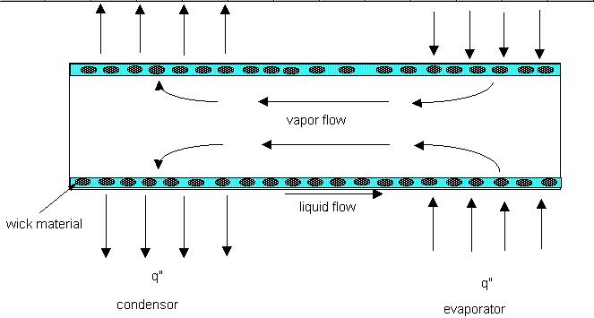
A heat pipe has three basic components. Some type of pressure cylinder, a wick structure and a working fluid. The figure below illustrates how a typical heat pipe might look. (Note: a thermalsphony, does not have a wick structure. While the two are in the same family the names are not synonymous. There has been some confusion and miss information on this point by people who should know better.)

In order for a heat pipe to operate, a number of things must be true. First, the pressure and temperature inside the pipe must be at saturation conditions. Second, one point of the pipe is receiving heat and another point is rejecting heat. Third, the summation of forces which bring liquid from the condenser to the evaporator must be greater than or equal to the summation of forces which retard the liquid from returning to the evaporator. The forces which return liquid to the evaporator are capillary and body forces. Those which retard the return flow are frictional and body forces. Yes, body forces can help or hinder the fluid motion depending of the orientation of the heat pipe.
Body forces are generally produced by gravity. Thus, if the evaporator portion of the pipe is below the condenser portion, then the body forces assist in returning the fluid to the evaporator. If the opposite is true, then gravity hinders the liquid return. Capillary forces are generation by the liquid surface tension. This effect can be seen quit readily when a soda straw is placed in water and the water climbs up the inside of the soda straw to some height above the liquid level in the container. The height climbed by the liquid is determined by the surface tension of the water , the radius of the straw and the contact angle between the liquid and the soda straw. This pressure differential is characterized by the Laplace-Young equation. Retarding forces, as mentioned earlier, may be induced by gravity. Frictional forces are generated from motion and are based on the fluids viscosity, speed and structure through which the fluid is flowing. In other words, a pipe flow problem. A number of tables are available to determine the pressure drop of a fluid as it flow through various wick structures. What I have just described is known as the capillary limit (the ability of the wick structure to pull liquid from the condenser to the evaporator) and the viscous limit (frictional pressure loses) of heat pipe operation. There are three more limiting operational points. The sonic limit results from choked flow occurring in the vapor flow (i.e. a Mach number of 1). (While start up of liquid metal heat pipes may exceed this limit due to extreme low density of the vapor, a blind eye is generally given to this situation.) The entrainment limit results when liquid is ripped from the liquid-vapor interface surface by high velocity vapor being transported to the condenser (yes, it happens. I have seen it.) The boiling limit results when the wall superheat causes nucleate boiling of the working fluid. This phenomenon traps vapor in the wick and blocks flow of the liquid to the evaporator. All of these limits result in dryout of the wick structure in the evaporator area and failure of the device.
Working fluids are selected based on the desired operating temperature range. This is only a partial list, many more materials have been used. Over the cryogenic region of 10K to 100K, Nitrogen, Oxygen and Hydrogen have been used. In the area of 100K to 500K, water, ammonia, methanol and some of the refrigerants are commonly applied. For high temperature applications, 500K to 5000K, metals such as Potassium, Sodium, Silver, Lithium and Cesium are used. Of course, compatibility of the heat pipe structure with the working fluid must also be met to avoid the generation of non-condensable gases.
So, there you have it in a nut shell. These devices are relatively easy to make, requiring only some screen for a wick, a tube (preferable copper), a vacuum pump and some pure fluid like distilled water. Although, the copper and water will react over time and produce non-condensable gas (NCG) and ultimately lead to heat pipe failure, it will work for a few months. Alternatively, I have made a pipe without the vacuum pump by heating a completely filled pipe with the working fluid and evaporating it from the pipe until a correct charge is left (enough to flood the wick at operating temperature). I then seal the pipe, which contains only the working fluid in liquid and gas form, before air can get into it. This method does not work very well because air does get into the pipe, but most of us don't have a vacuum pump sitting around.