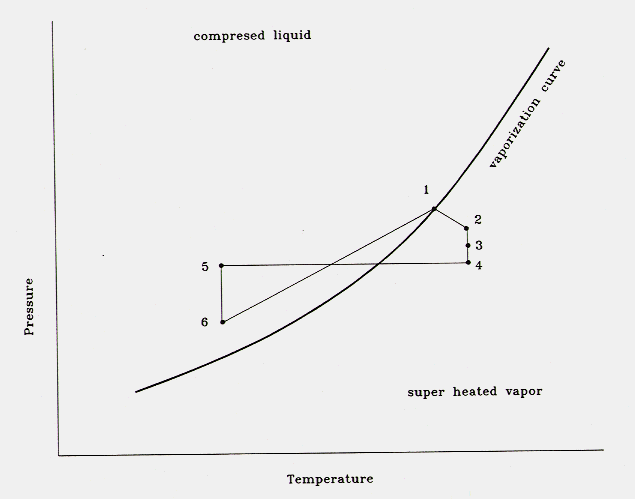

were the numbers correspond to the physical locations indicated below.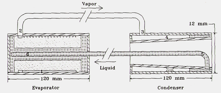
Additionally, the wick structure, which is responsible for transporting the liquid from thecondenser to the evaporator, does not run the full length of the liquid path. In fact, the wick iscontained only within the evaporator section, a very small fraction of the total CPL length.
A CPL can transport large amounts of heat over great distances, (the test apparatus was 3meters long and is attached to the board which spans the picture diagonaly.)
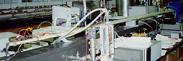
with very large adverse hydrostatic heads. Additionally, the small size and flexibilityof the fluid lines allow the CPL to be installed in electrical conduit. A big advantage when youare saving space and you don't have a straight line from the heat source to a heat rejection point which is the case for space craft and electronic components.The model is based on the Clausius-Clapeyron equation and the pressure variations caused byfluid flow, gravity and surface tension. The model results were then compared with experimentalwork.
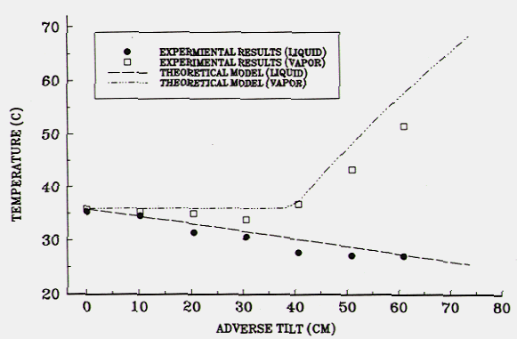
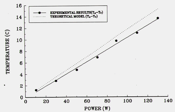
One very interesting conclusion of this work is, if the wick structure were composed of a highlynon-conducting material, the CPL performance and ability to operate at greater adverse pressuregradients, would improve. This suggestion was first noted in a paper by Dickey, J. T.and Peterson,G. P., "Experimental and Analytical Investigation of a Capillary Pumped Loop", Journal of Thermophysics and Heat Transfer, Vol. 8, No. 3, July-Sept. 1994