printer port robot
only works with windows 98 or pre-windows 98
The pc printer port can usually be switched on & off using one of the following
lines of QBASIC
OUT 888,0
OUT 632,0
The number'0' is altered according to which wires you want switched on or off.
Either one of these lines constitutes a program, you have to run it for it to work.
Although the printer port has 25 connections, only 8 of them are switchable outputs.
Here 4 of these outputs are being used to control a simple robot
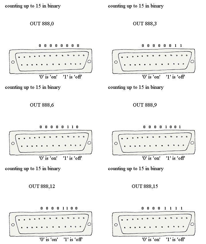
The desired permutation of 'ons' and 'offs' is obtained by using a binary number.
For example the binary number 0101 (of which the decimal equivalent is 5) will switch
both motors on forwards.
Try the first of the QBASIC lines with this number
OUT 888,5
and see if anything happens. If nothing happens, try the other one
OUT 632,5
The first one usually works.
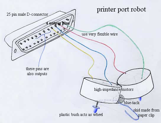
The reason the robot has no wheels is that the printer port only just supplies enough current to run a high-impedance motor (walkman motor or Mabuchi solar motor) quite slowly; any form of cheap
gearbox will inevitabley jam. By using the motor axle as a wheel you achieve a gear-reduction without any gears. Putting a plastic bush on the axle improves the grip.
Usually the printer port would be used to switch transistors which would in turn switch the motors, however this makes it a lot more complicated.
Assuming that the first of the QBASIC lines worked, the other ones you need will be
OUT 888,6
(first motor reverse, second motor forward- '6' is the decimal of binary 0110)
OUT 888,9
(first motor forward, second motor reverse- '9' is the decimal of binary 1001)
and finally
OUT 888,10
(both motors on reverse- '10' is the decimal of binary 1010)
OUT 888,0 switches both motors off.
Binary numbers up to 11111111 (decimal 255) can be used to switch all eight outputs.
An easy way to create a time delay is with a for-next loop, for example
FOR n=0 TO 10000: NEXT
will create a short but perceptible time delay, its precise length will depend on the speed of the computer's processor. To make the delay longer, use a bigger number
FOR n=0 TO 70000: NEXT
a smaller number will give a shorter interval.
This program will switch both the motors on briefly, then reverse just one of them
OUT 888,5
FOR n=0 TO 9000: NEXT
OUT 888,9
This animation illustrates how binary numbers are used as a way of controlling outputs
Another use for outputs is to switch LEDs, here two LEDs are connected to the first two outputs and to the printer port earth via a 10 ohm resistor. The resistor is to limit the current and probably isn't necessary
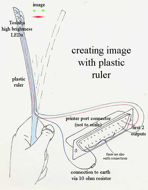
if the LEDs are switched on and off using the following program and the ruler is waved rapidly back & forth the image of a face will appear
w=10
WHILE INKEY$<>CHR$(27)
OUT 632,2
FOR n= 0 TO w:NEXT
OUT 632,1
FOR n= 0 TO 5 * w:NEXT
OUT 632,2
FOR n= 0 TO w:NEXT
OUT 632,0
FOR n= 0 TO 15 * w:NEXT
WEND
The variable w defines the width of the image; the multiplier 5 defines the width of the mouth; 15 defines the space between the faces. The program keeps going round the WHILE-WEND loop until escape is pressed (escape is ASCII code 27).
If the program is made more sophisticated the face can be made to wink etc, using more LEDs (up to 8 can be used altogether)will permit much more interesting images. A much better way of doing this is by using a Nipkov disc.
using inputs
If the following program is run
PRINT INP(889)
a number will appear on the screen, for example 120.
If a wire is now connected from the earth pin on the printer port to one of the input pins
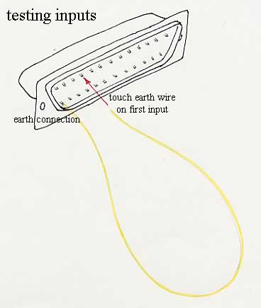
and the program is run the number should change. The new number might be 56 for example.
If you found that the printer port responded to the number 632 then the program should be
PRINT INP(633)
There are five input pins altogether. Earthing the other ones should produce different numbers, for example 248,88,104,112. Don't try to understand the significance of these numbers- I never do. The same pin will always produce the same number. Earthing different permutations of the pins will produce different numbers again.
This is a slightly better program for showing this
WHILE INKEY$<>CHR$(27)
PRINT INP(889)
WEND
This means 'keep going round the loop while escape is not being pressed'; it continually shows the number which corresponds to the earthing or otherwise of the input pins.
Having established that the two numbers 120 and 56 say indicate whether the earth connection is touching the first input pin you can make a collision switch for your robot
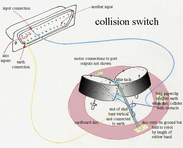
and write a program for it
OUT 888,5
WHILE INKEY$<>CHR$(27)
PRINT INP(889)
WEND
This is just like the last program, but it has an extra line that switches the robot on
OUT 888,5
WHILE INKEY$<>CHR$(27)
IF INP(889)=56 THEN PRINT "there has been a collision"
WEND
OUT 888,0
Again very similar except it switches the robot off when you press 'escape'. What you really want is a program which says 'reverse if you hit something'
OUT 888,5
IF INP(889)=56 THEN OUT 888,10
Unfortunately this only works for one collision, it would be better if it said 'if you hit something then if you had been going forwards go backwards, otherwise go forwards (because by implication you must have been going backwards to begin with).
This is a good illustration of the difficulty of translating common sense into logic. Because we develop common sense naturally (if we are lucky) we are unaware of its complexity.
d=5
WHILE INKEY$<>CHR$(27)
IF INP(889)=56 THEN IF d=5 THEN d=10 ELSE d=5
OUT 888,d
WEND
OUT 888,0
This introduces a variable, d (it could be called anything) which is used to describe the direction of the robot.
In practice this doesn't work very well because the computer goes round the loop thousands of times a second and when it collides with something it tends to get smitten with indecision. This can be fixed by introducing a time delay: 'if you've hit something back off a bit before asking yourself if you've hit anything again'
d=5
WHILE INKEY$<>CHR$(27)
IF INP(889)=56 THEN IF d=5 THEN d=10 ELSE d=5
OUT 888,d
IF INP(889)=56 THEN FOR n=0 TO 1000:NEXT
WEND
OUT 888,0
Even an apparently simple physical system can have undreamed-of snags.
Mechanical ingenuity can be a much more powerful design tool than electronics.
more inputs
In my example, the second input gives the number 248 when it's earthed. If the first input is earthed at the same time it gives the number 184.
It's possible to isolate the inputs by 'binary anding'. If either or both of the two inputs might be earthed, the following will isolate just the first one
PRINT INP(889) AND 248
this will give 56 even if they are both earthed; similarly
PRINT INP(889) AND 56
will isolate the second input.
This is really all the programming knowledge you need to read PWM (pulse width modulation); there are now many cheap but sophisticated sensors on the market which use a PWM output, for example
ultrasonic eye
electronic compass
accelerometer
colour detector
another colour detector
assuming you connect the PWM output from these devices to the first input (you also have to connect the earths together), the following program will give a number which indicates accelaration, colour etc
WHILE INKEY$<>CHR$(27)
n=0
WHILE INP(889)=56
n=n+1
WEND
PRINT n
WEND
a simple interface
The golden rule of electronics is 'it doesn't work'.
The skill lies not so much in building things but in finding out why they don't work when you've built them. This is an interface designed with this rule in mind
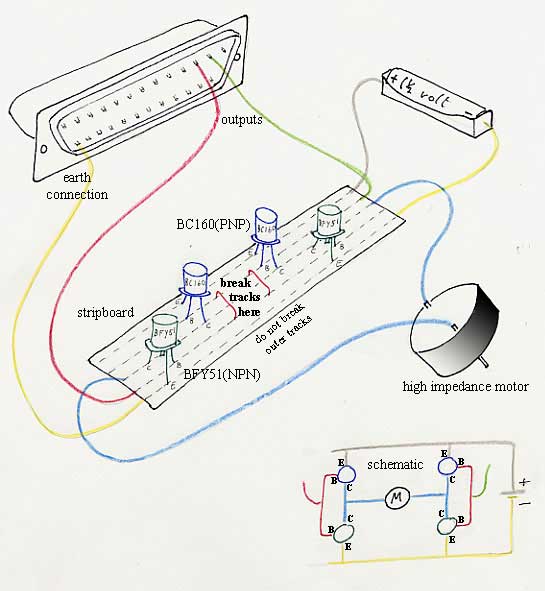
It uses just 4 commonly available transistors and nothing else, because they are arranged symetrically on the strip board it is topographically simple, notice the earths are connected. It's very unlikely that you'll damage anything with just a single battery, also it gives a very consistant current, suitable for a writing robot.
The interface will respond to the binary numbers 00,01 and 10 (decimal 0,1 and 2) so the program
OUT 888,2
will switch the motor on in one direction
OUT 888,1
will reverse it, incidentally the equivalent command in 'C' is
outportb(888,1);
the input command is also very similar
inportb(889);
you have to include "dos.h". I have never been able to find a good reason for not using QBASIC. Apparently you can even do it with
java.
sensing a voltage
Sometimes you want to measure a voltage level rather than just sensing if something is on or off; this can be done by measuring the time it takes a capacitor to fill with electricity using a for-next loop
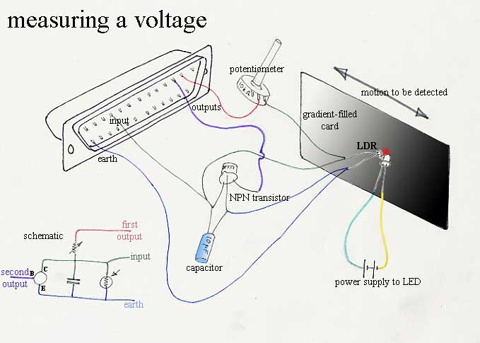
The transistor is controlled by the second output wire (the first one is just being used as a power supply and is always on); when the second output is on the transistor conducts and empties the capacitor (the first for-next loop in the program does this). As soon as it switches off the capacitor begins to fill through the potentiometer. How long it takes depends on how well the light dependant resistor is conducting, a bit like filling a bath with a leak in it. To complete the analogy, if the LDR is the leak, the potentiometer is the tap and the transistor is the bath plug.
WHILE INKEY$<>CHR$(27)
OUT 888,3
FOR n=0 TO 1000:NEXT
n=0
OUT 888,1
WHILE INP(889)=56
n=n+1
WEND
PRINT n
WEND
The value of n keeps getting bigger until there is enough voltage to switch the input (1.3 volts) and then it's displayed on the screen.
The more conductive the LDR is, the higher will be the number on the screen. The LDR is shown looking at a gradient-filled card which is illuminated by a Toshiba extreme-brightness LED. This works as a very good frictionless linear motion transducer

it can also be used as a rotary transducer

patterns on eggs
machine vision
back to main site
my email is davidvwilliamson@hotmail.com


