soup tin stirling engine
The very first stirling engine I made hardly worked at all: it would spin one way slightly easier than the other, but that was the only sign of life. It wasn't until I found Saburo
Tsucchida's page that I finally made some progress. The reason was that I now understood how it was supposed to work, whereas before I had made one without understanding what I was making.
I devised an experiment which was the key to my ultimate success: I made a closed cylindrical paper box which fitted loosely inside a soup tin and was about half the height. Then I stretched a balloon over the open top of the tin & held the bottom over a candle flame with my index finger gently touching the middle of the ballloon. When the bottom of the tin was hot I turned the tin upside-down, then right way up, then upside-down again so that the paper box fell up & down inside the tin.
I could feel the balloon expand & shrink with my finger because of the displacement of the air from the cold to the hot end of the tin and back again. Because I could actually feel the force that was supposed to be driving the crank I understood what I had to do to make the engine work.
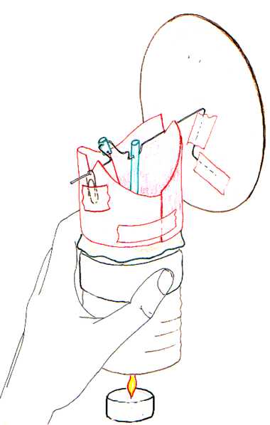
This is an
engine which was the direct outcome of my experiment.
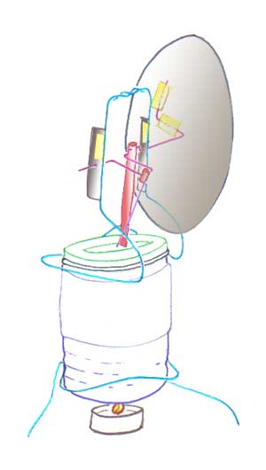
It will go at 50-90 rpm depending on the state of the night-light, faster with more night-lights,
alternatively it will work with a 60 watt spotlight held near the base. It is
cooled by a water-soaked paper towel wrapped round the tin. The large cardboard
flywheel enables it to run at very low revs whilst subjecting the cardboard
bearings to very little stress. Although cardboard would at first seem an
implausible material for a flywheel in fact it is very good because it has a
very high inertia for a low weight.
The engine is supported by a bent wire clip, although you can hold it
by the paper towel if you don't want to make a support. A similar wire clip holds the crankshaft bearings which are simply holes
in slips of card taped to the clip. The clips grip the grooved side of the
tin.
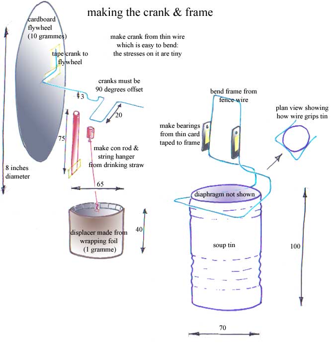
Perhaps the first part to make is the displacer; you can make it out of paper however in the diagram I have shown it made from wrapping foil. Wrapping foil
is much more delicate than paper. It isn't like a piston in a cylinder, all it
does is displace the air from one end of the tin to the other and back again. So
its fit in the tin is not in any way critical, it just has to be able to move up
and down without jamming. If the top is made slightly indented you can use your
finger and thumb to squeeze the glued surfaces together. More detailed instructions are at the bottom of the page.
The con rod is made from a bit of drinking straw with a pinhole for the big end bearing; the little end bearing is made by squeezing a tab of sellotape over the end of the straw. Just lately I found a way of doing it without a little end bearing ie with the connecting rod attached rigidly to the washer.
The displacer is moved by a bit of invisible mending thread tied to a string
hanger; the string hanger is made from another bit of drinking straw.
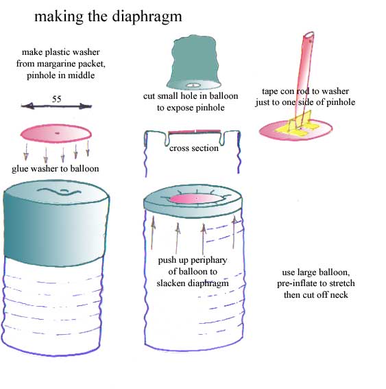
The diaphragm is made from a (not
very) large party balloon with a washer glued to it; the washer has a pinhole
which serves two purposes: to enable the thread to move the displacer and to
equalise the pressure inside & outside the tin. It does this much too slowly
to interfere with the cyclic pressure change in the tin.
The balloon should be pre-inflated to stretch it then placed over the top of the tin so that the
center is flat but not stretched. The washer is cut from thin card or a plastic
margarine packet. After making the pin hole it is glued to the balloon; I used
super-glue but other glues might also work. The periphary of the balloon should
be pushed up the side of the tin so that the washer is held by a completely
loose collar of rubber. Before doing this the diaphragm must be removed from the
tin to cut away the middle of the balloon and expose the pinhole. The thread can
now be passed through from the displacer to the string-hanger and the diaphragm
replaced.
Tying the thread to the string hanger is very fiddley, you have to
get the length just right so that the displacer moves up & down without
jamming at the top or having undue slackness at the bottom.
The diaphragm is the most critical component and deserves a lot of attention, the rest of the
engine will probably be OK if the diaphragm works. A balloon is of course a very
worthwhile plaything in its own right and sacrificing one to make a stirling
engine may not necessarily be the wisest choice. If you don't have a balloon,
you can make the diaphragm out of thin polythene, in this case stretch it tight
as you would make a top for home-made jam. Stick the washer to it with a thin
bead of sellotape. The polythene will have enough flexibility to allow the
washer to move up & down. This isn't as efficient as the balloon diaphragm,
it requires two night lights to make it run. However it removes the costliest
component (the balloon) and it is easier to make.
I strongly recommend
reading Koichi
Hirata's instructions for doing this as they are much more exhaustive than
mine, I have just modified them so that it can be made with very few tools or
skills; I changed his method for making the diaphragm, which involved reducing
the throw of the crank from his 8mm to my 3mm, also his method for making the
displacer. I found that the engine works with only one con rod in the middle of
the washer because the thread can be pulled by the string hanger at a slight
angle; otherwise the designs are the same.
The engine will only run in one
direction: the string-hanger crank leads the con rod crank by 90 degrees.
why doesn't my stirling engine work?
Because the throw of the con-rod crank is too big, this causes the flywheel to try and drive the
diaphragm. I found it works quite well with a crank throw as little as 2mm,
however because it's so difficult to make it so small you can achieve the same
thing by simply making the flywheel-end crankshaft bearing an open V shape, the
crankshaft just rests in it & lifts out of it briefly on each rotation, but
I don't think this takes any energy out of the system. Anyway it stops the crank
jamming against the diaphragm.
Because this reduces the bearing forces to nothing at all it means you can make the whole top end out of a piece of folded card; it's much easier to fit the crankshaft because it just rests in two 'V' notches, you can constrain one end with a paperclip sellotaped to the card. A
polythene diaphragm is now just as efficient as one made from a balloon because
the floating crankshaft bearing does what the elasticity of the balloon was
doing. So you don't need to use superglue.
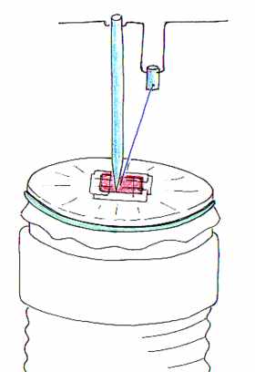
If the washer is made about one
inch square it is very easy to sellotape it to the polythene. This works better
than a larger washer, also because there is a lot of space round the edges you
can watch the displacer going up & down if you use transparent polythene.
The polythene should be a bit slack.
As the stirling engine heats up the
amount by which the air expands and contracts changes. So ideally the crank
should have a variable throw, and the loose bearing seems to achieve this.
Incidentaly this is the same reason why Newcomen steam engines were only very
seldom used to drive rotating machines
It starts much quicker if you
use a coke can instead of a soup tin, because the metal is about one-quarter the
thickness.
If you use a coke can you then have the problem of cutting the top
off the can, if a jagged edge is left this will puncture the diaphragm. It also
weakens the top of the can which makes fitting the diaphragm a bit
difficult.
It's a good idea to make the big-end bearing out of a plastic
bead, you can attach the connecting rod to it with sellotape. The force on the
big-end is quite large so it's a significant source of friction.
I've had a lot of trouble with the polythene leaking, even a small leak will reduce the
engine's power or stop it working at all. There are two causes of leaks: the
first one is the top of the coke can where you've cut the metal remains jagged
and unless you cover it with sellotape you get holes. The second one is leaking
past the rubber band. When you've taken the polythene off about twenty times the
sellotape starts to accumulate on it and make it too stiff for the rubber band
to create a seal. You can sometimes spot this because the fumes from the candle
get sucked under the polythene into the tin and form condensation inside.
You can increase the rpm by reducing the stroke of the displacer, although this also
reduces torque so I don't know if you get any overall increase in power. The
thing is you can quickly do meaningful experiments of this kind.
I think it helps to insulate the base of the displacer with about two fluffed-up cotton
buds. Just put them inside before you glue the top on.
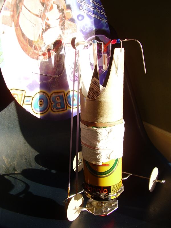
This is a loco made with a 500ml
aluminium can, the displacer is 90mm high with a clearance of about 2mm. The
washer is 35mm diameter. It doesn't go very fast
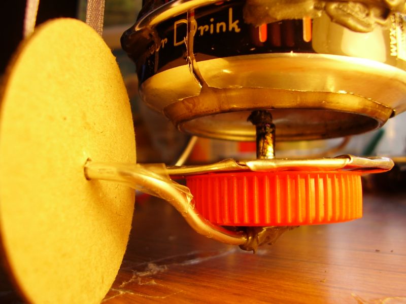
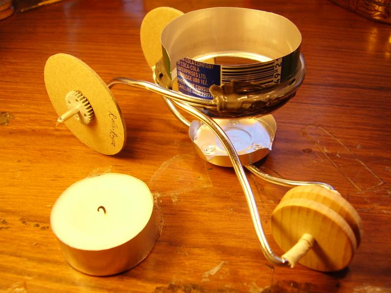
This is the chassis, it's made from a bit of bent aluminium wire
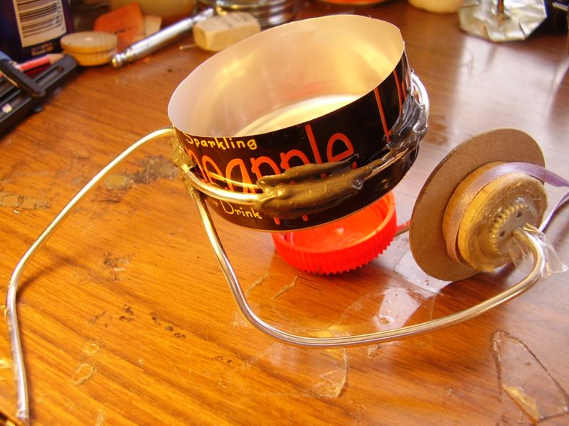
it has a holder for the engine made
from a coke can, a driving pulley and a bottle-top burner. This shows fitting
the meths burner
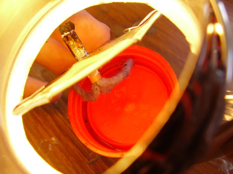
This is a side view of the assembled burner with the engine in the holder
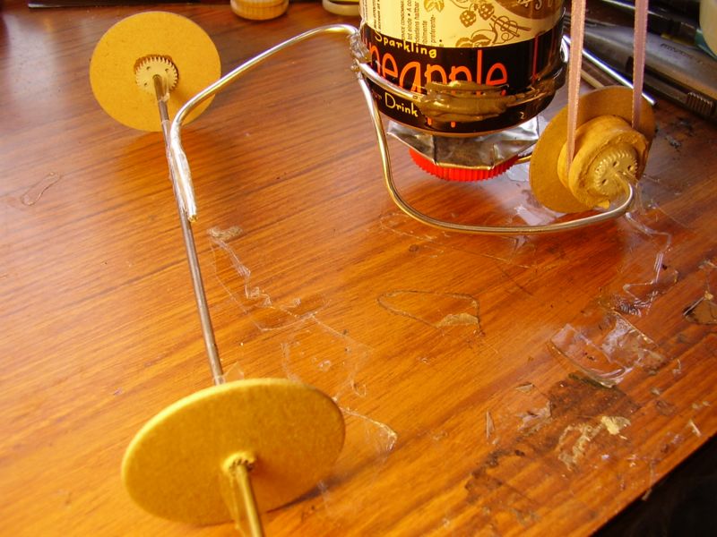
This shows the axle and wheels
sellotaped to the bent wire & driving band made from a length of ribbon
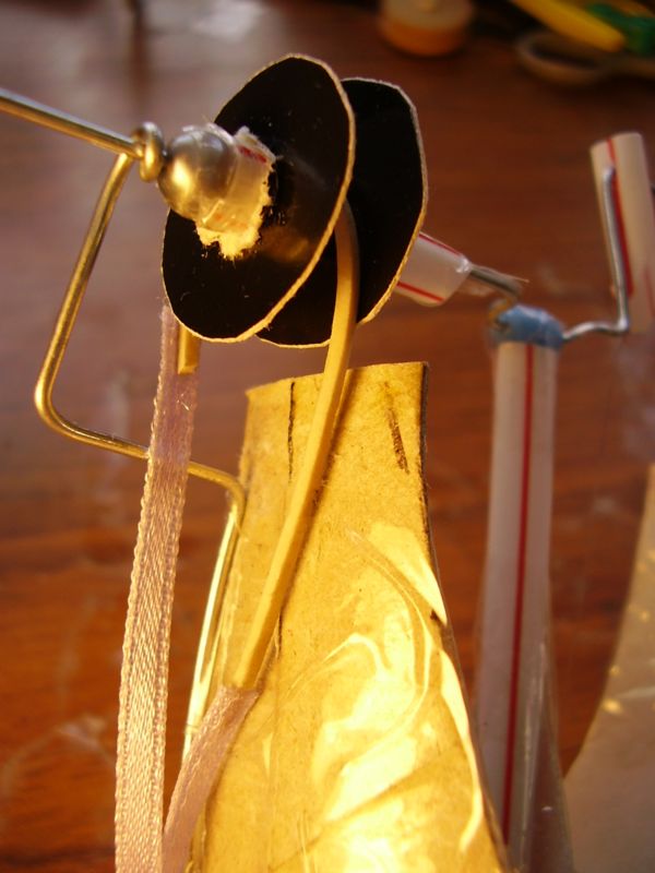
This is a detail of the
top end of the driving band, it is spliced with a short length of rubber band to
keep it in tension
The bearing point is between the pulley and the flywheel, this is so that the weight
of the flywheel and the tension of the driving band tend to balance each other.
This is one made from a mini coke can
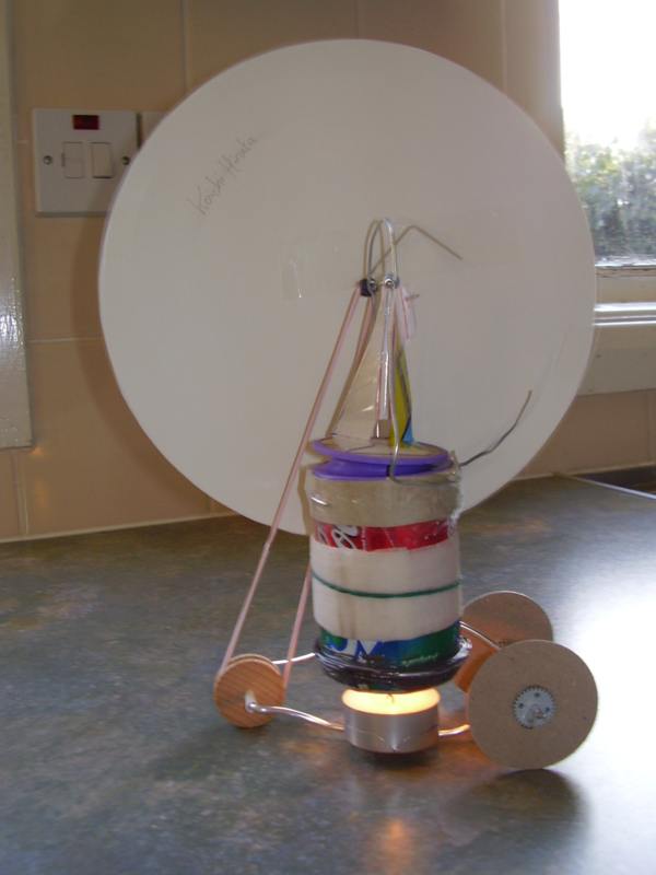
It's a lot neater. The displacer only has a 10mm stroke, it is only about 15mm shorter than the tin. I have recently found it's better to use a narrow 250 ml soft drink can (ie this diameter but taller). See further down the page.
This is my latest design, it's much simpler to make
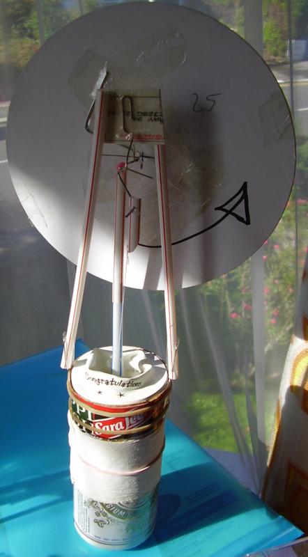
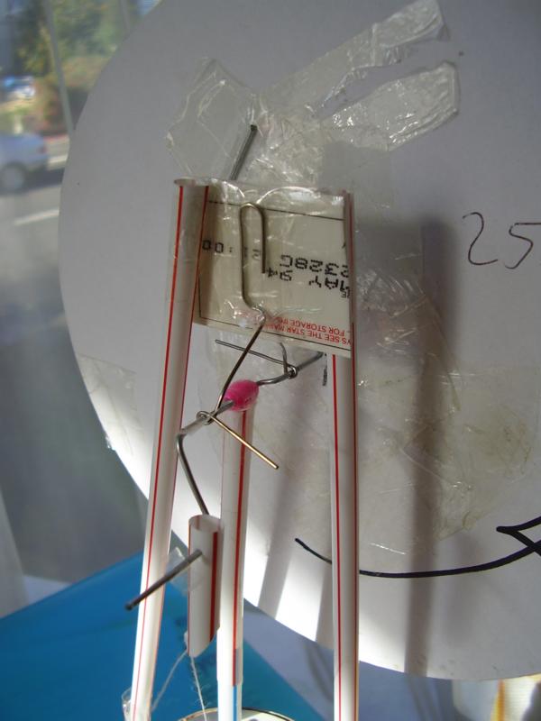
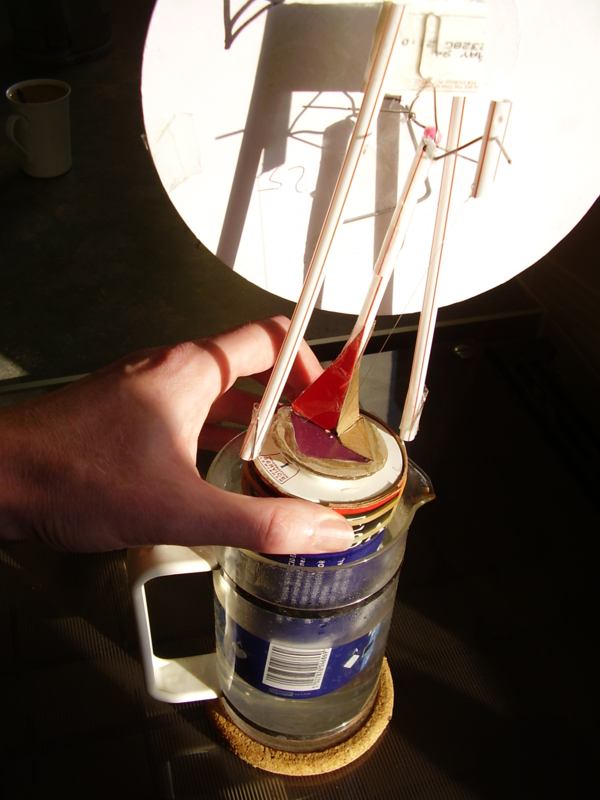
here with more efficient
diaphragm running on the heat from boiling water
Here made with a plastic bottle -
in fact it's a tennis ball container with a reinforced rim
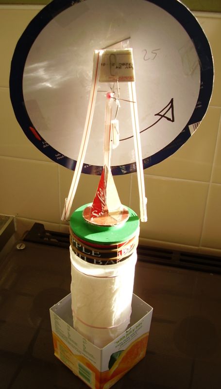
The orange juice box contains
the hot water. I found it would run at 50 degrees if I cooled the paper towel
with an electric fan. 55 degrees without the fan. The plastic begins to distort
at about 80 degrees centigrade.
This is a detail of the efficient diaphragm. You can see the top
of the displacer inside the bottle
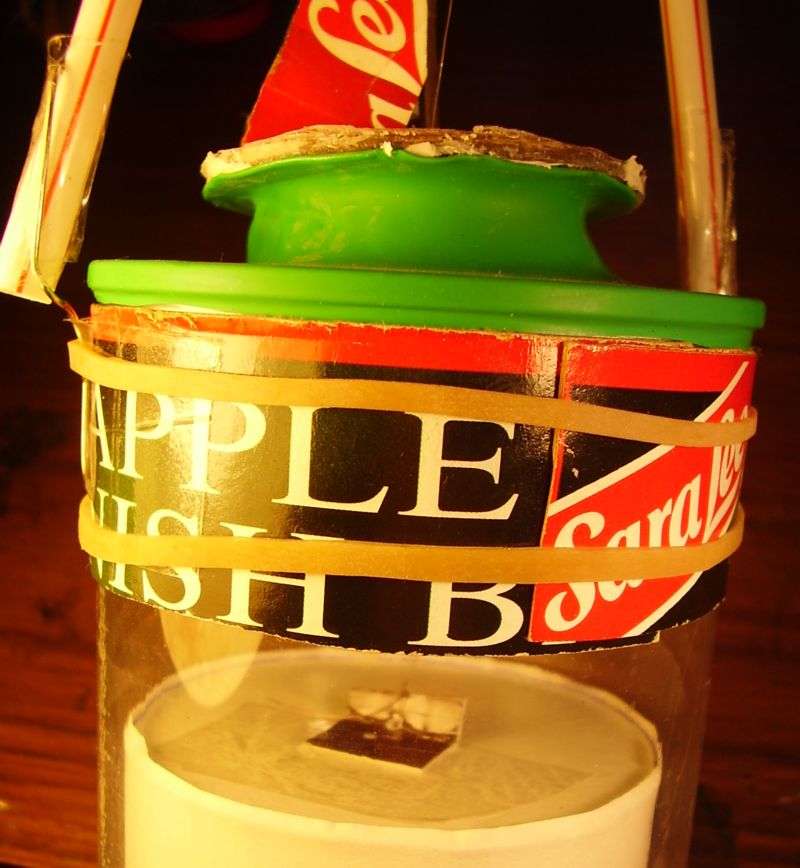
More efficient one using two 2-litre plastic bottles slightly different diameters to form air-tight seal, coke-can mechanism glued into top
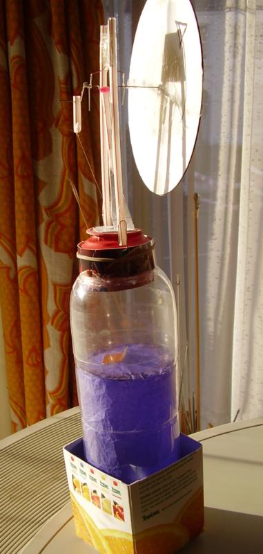
It needs a temperature difference of at least 30 degrees celcius between the bottom & the top, you can do this by putting either hot or cold water round the bottom. If you use cold water you have to add salt to ice to achieve minus 10 degrees. I found an easy way to do this is scrape ice off the inside of a freezer with the rim of a metal thermos flask, then add a lot of salt and some water. Don't fill the flask completely. Now put the lid on & shake vigorously; the resulting salt/slush mixture should be cold enough to work the engine. The engine runs backwards if you use cold rather than hot.
making a displacer out of paper
The first bit of the engine to make
is the displacer. Make a former out of a mini coke-can with card & paper
wrapped round to give the correct diameter.
This shows checking the diameter of the former
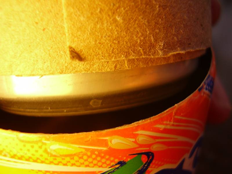
Use the former to make a paper cylinder: cut a fringe round one end & fold inwards
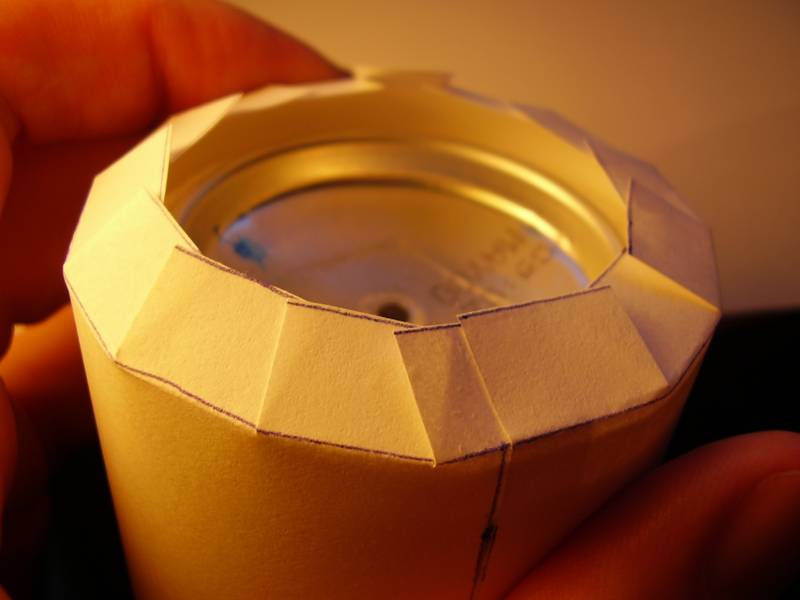
glue on a paper
disc
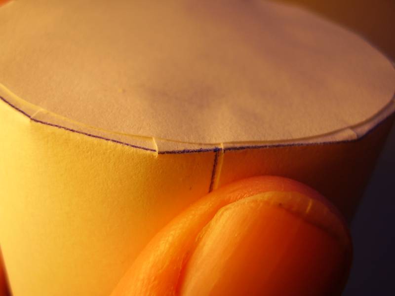
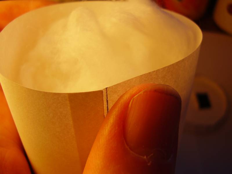
remove the former
& fill the cylinder with three fluffed-up cotton buds
make a top end out of a paper disc
with folded-up fringe, glue in place with PVA
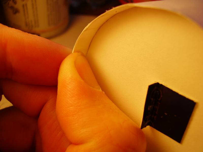
view of completed displacer inside
tin. Note cardboard string-hanger
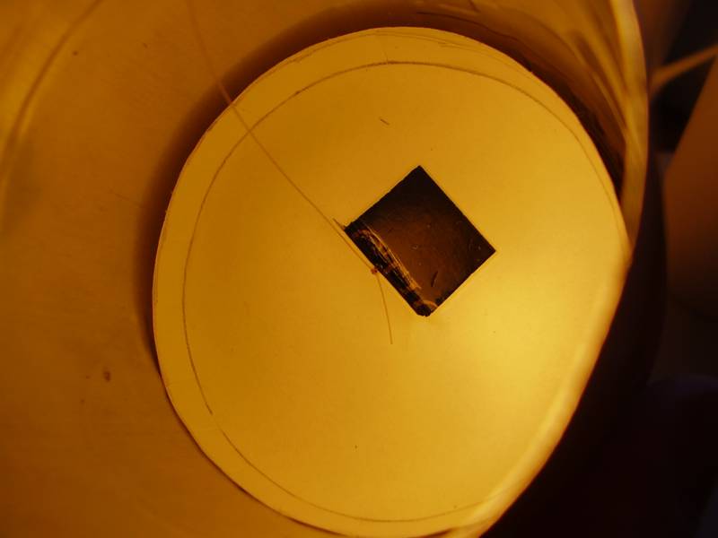
This is a much simpler displacer made from a toilet roll with the ends blanked off with two cardboard wheels
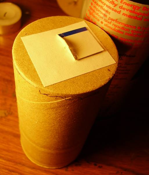
The diameter is by coincidence a loose fit in a narrow 250 ml soft drink can, it is at least twice the weight of a paper displacer but this doesn't seem to effect the motor's efficiency. It is the best combination I have yet found for making a locomotive, I used a 20mm stroke.
making an efficient diaphragm out of a balloon
Stick cardboard disc to pole of inflated balloon with superglue,
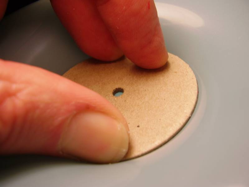
allow balloon to deflate slowly, cut off neck of balloon
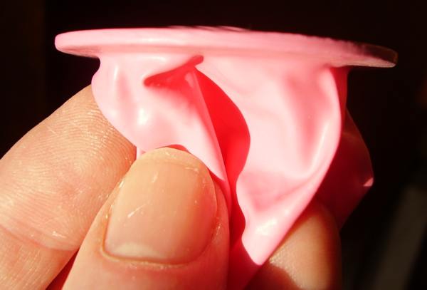
turn inside out
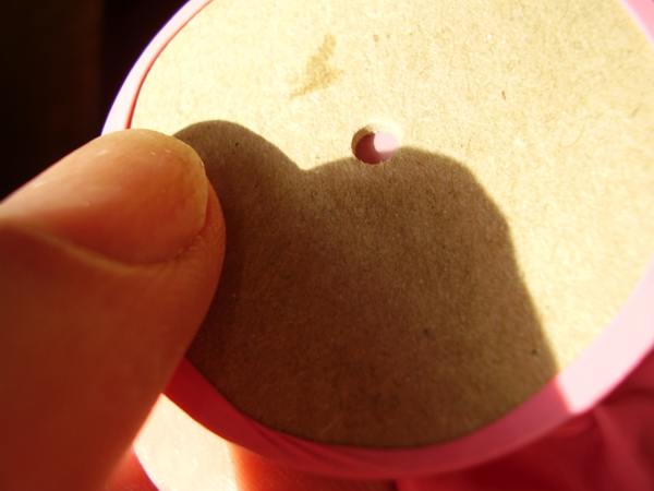
Cut away center
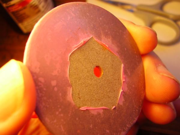
stick card square on other side, make pinhole
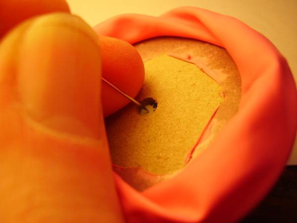
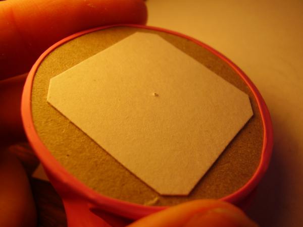
thread through pinhole, support structure for connecting rod
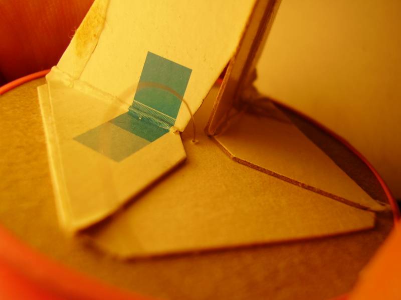
The tension of the latex in the diaphragm seems to effect the motor's efficiency enormously. You can adjust it by changing the length of the connecting rod or by changing the extent to which it is pulled down round the sides of the tin. A few millimeters of adjustment can make the difference between the engine running fast & it not working at all. It should just have any slackness pulled out of it so that it makes a perfect concave annular shape without having any undue tightness.
movie of latest loco: 20mm stroke (displacer) 5mm stroke (diaphragm)
1000rpm stirling engine made of tin cans
stirling beam
engines
airmotor that works by blowing in it, will also run on steam
whispergen central heating boilers
wood chips
wikipedia on stirling engines
stirling engine fan you put on wood stove to waft the heat in your direction
stirling engine loco, only £280, nice musical box feature
slightly more affordable coffee-cup engine
stirling engine flying machine
my email is
davidvwilliamson@hotmail.com
back to main site


