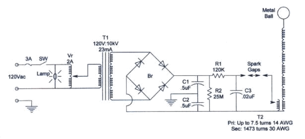
Theory for Circuit
The VR
gives 0-120VAC to T1 changing the output voltage. Zero to 10000VAC output
going into the BR creating a full wave then filtering it with C1 &
C2. This creates a voltage control from 0-14140VDC. Being an unregulated
power supply it's current is limited by R1. R2 is just being used as a
bleeder. Tesla's spark gap design for generating high frequency works well
for making the RF. With the C3 & T2 pri you get the parallel LC circuit
that needs to be tuned to the right frequency, this way you get low current
draw across the supply while getting larger voltage drop across T2 pri.
T2 has a high ratio in turns & knowing that the primary already has
high voltage on it, the secondary you know is a lot larger. Now the T2
sec is in series with metal ball which has capacitance so you have a LC
circuit that's in series. So by changing the amount of metal on top you
can tune it.

Understanding my reasoning
When I design this tesla coil there
was a good thought I had. Why not try to increase the current to.
If you look at the circuit closely you will see that if you put a ground wire on the ball you'll short C2. Being that both sides of T2 are low impedance the current goes high. When the tesla is active the R.F. arc's coming off it act as a short. By putting a ground rod up close to the arc's you'll get a high current discharge pulse from C2. Current rates were measured at a peak value of 3445 amp having a time of .5 miro sec's. The sound is like a .5 microF cap with a voltage level of the tesla coil being discharged with the old handy screw driver.