![]()

|
|
|
| Big, powerful solid-state monster amplifier | |
| Big amp is monster. If you have needs for power, and 100% reliability, this is a masterwork for you. This amplifier is constructed to be a real high-end amplifier for my friend and his Martin-Logan CLS. He tried everything on market, from Rotel to Pass. Nothing was capable to drive this electrostatic monster speakers, with their 0.5 Ohms at high frequencies. Then I developed Bigamp. We arranged listening session. With such ease and grace my amp delivered every music material, we started with classical music, ending our session with new albums from Page & Plant, Seal and others. After this torture amp look at us with a smile, what was big surprise, because most amplifiers rapidly overheating on this speakers. After this one, several copies have been built when power was needed-from disco to studio use. |

|
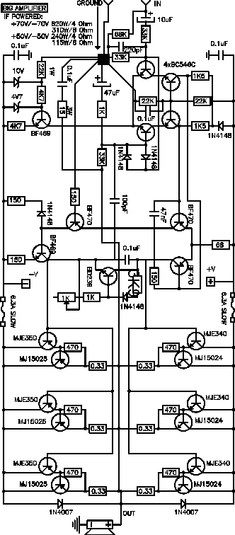
Electronically amplifier is pretty much straight-forward, but nothing is here by accident. My first rule was: big, powerful, reliable, nothing fancy. Ten years ago, I will design something crazy, trying to apply everything what was new, but this always has ended in 10 minutes or hours of glory (read smoke). Looking from distance at those times, I designed real piece of reliability, and this was like ending a search for holly grail. Most of us, do not want to design and make boring and deja-vu things, but, however, most of us have ended this quest or search when some piece is great in every aspect-and does not die for no reason after few months.
Topology: Cascaded differential input, but single ended - what was surprisingly enough for everyone who knows my work. But this front end, especially if you can find BC546-but with rare C suffix (hFe >400) or such MPSA 06 (very hard to find) is fast, and because high output some input signal attenuation and limitation is applied (signal limiting diodes are two 1N4148 connected between bases of input transistors-you can remove them, if no future abuse is planned). Other substitutions are easy to apply, but I had some stability problems with transistors other then BC546C. This input stage deliver signal to second, voltage gain stage, again differential, but with some tricks. Both input stage and voltage gain stage are supplied from current sources (BF469). This combination is fast, reliable and without stability problems. Vbe transistor is BD243 in TO-220 case, and MUST be mounted on output stage heat sink (isolated, of course). He is responsible for output stage idle current-approx. 60 mA per one output transistor (measure 20 mV on each 0.33 Ohm/5W emitter resistor). Output stage is somewhat unusually designed, because every output transistor (MJ15024/15025) have his own darlington mate (driver) MJE340/350.
Power supply must deliver POWER. This means min. 600VA toroidal transformer with 2x40-2x50 ACV secondary (depends how much power you need. Needed dual DC voltages for different output powers is on the top of schematic. 4 electrolytic capacitors 10000uF/100V and diode bridge 45A for each channel. Wiring must be min. 6qmm in power supply, output transistors must be connected with PCB with min. 1.5qmm wire. Heat sinking must be adequate, around 0.5C/W per channel. I usually use heat sink 300mm long, 150mm high, with 40mm fins, and then mount output transistors on extruded "L" aluminum profile 40x40x4. I have not found anything critical in this whole concept. Only standard rules in building this amplifier must be applied, even with if some budget limitations are done-single transformer, bridge and four 4700uF/100V for both channels works fine. This monster easily deliver his full power in any case and without problems. Only thing recommended is some kind of delay-offset protection circuit (you will find something on our pages in future). Everything else is up to you, and remember, this amplifier is by itself project for advanced amateurs. If you have additional questions, send us E-mail, and please, be very specific.
Back
to Welcome
Bigamp PCB
| Bigamp
PCB components layout
New PCB 2003.
This document maintained by
Drazen
Zeman. E-mail us .
Material copyright © 1999.
DRAZEN ZEMAN