![]()
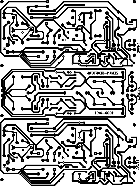
PCB for tube linestage preamplifier
![]()

| PCB look is from upper (component) side. This is a good thing if you print this board. Printed side of paper or foil goes directly in contact with copper. |
| Important notice: PCB presented here are not 100% graphically correct. However, they are electronically OK, but they are made some time ago, mainly in DOS, then few times converted (plotter files in cdx, then in GIF), and those conversions and graphic formats are not 100% compatible. So, you can used them as they are, after re-checking, or you must convert size and-or format. |
| Components layout and PCB show newest version of our Linestage. Few modifications have been done. Zener diodes in power supply now are supplied with current not from resistor (as in shematic), then from much quieter current source (one MJE350, two diodes and two resistors per channel). |
Linestage schematic|Welcome
Linestage
general| Component
layout
Material Copyright © DRAZEN ZEMAN 1999. .

