This page is designed to give some preliminary information about my stepper motor boards. This will ensure that the user will understand the differences between different models ans possibly make the best choice based on the application. If you are only interested in the products, please scroll down the page.
What is R/L Driver:
The time constant of an inductor series with a resistor is L/R. It
means that the Smaller the L or the larger the R, the faster the winding
will get to its maximum current. This is why in older motor driver circuits,
the designers would put a powre resistor with the winding to help the time
constant. Benefits: Faster time constant. Weaknesses: Excess
heat dissipation, Less reliability, Higher cost, Unflexibility. The reason
why the design is not flexible is if the motor or powersupply or the current
change, you must re-calculate the resitor values and must replace them
every time you change anything in your system. None of
my boards is R/L conrtoller.
What is PWM:
PWM stands for Pulse Width Modulation. In this technique, the power
supply voltage will be switched on the motor windings at full. Once the
current reaches a certain value which is set by the user, the feedback
paths of the PWM circuitry will eliminate excess curent flow. In this technique
there is no need for high power resistors used in R/L systems. Benefits:
Since the whole power supply voltage drops on the winding at start, it
will have the benefit of fast rise time that a R/L driver has, but non
of the weaknesses exist any more: Regardless of the powersupply voltage,
the current is controlled by shunt resistors, thus changing the powersupply
will not cause any change in the circuit. If you change the motor, the
only thing that you must set is the current setting or shunt resistor.
In my boards the current is set by three switches for each motor, giving
a high level of flexibility. Weaknesses: Hard to design, but thanks
to Allegro Microsystems and ST Microsystems who have the PWM controllers
and drivers integrated in off the shelf ICs. No Weakness!!!!
What is Unipolar:
In unipolar drivers, the direction of the current flowing in each winding
is constant and thus in order to reverse the magnetic field, the motor
must have windings that can be energized individually so that the controller
be able to set the direction of each winding independently of the others.
All 4, 5, 6 and 8 wire stepper motors are capable of Unipolar control.
Benefits: The energy is stored in one winding at each cycle and thus is
easier to discharge the energy. Benefits: Good for higher torques
at higher speeds. Weaknesses: Very hard to cotrol for fine resolutions
like Microstepping.
What is bipolar:
The motor is configured to have only two windings. This means that
for 6 wire stepper motors, the center tab of each side of the motor must
be ignored and not used. And for 8 wire motors, it must be wired in either
series or parallel configuration, so that only 4 wires be available. And
this is how it works, each vinding can be charged from -I to +I, where
I is the maximum current set by the controller. The current direction is
controlled by the driver and thus changing the direction of the field is
done by each winding. Benefits: Very smoother moves. Easier to control
in microstepping applications. Good for applications which need the smoothness
of the moves but not requiring higher torques at higher speeds. weakness:
Not optimized for applications with high torque at higher speeds.
Products:
All the following products have the same following features unless
specified in individual notes:
- PWM controlled. Dedicated translator chips to make ease of use with
step and direction control signals.
- Step/ Dir and Enable pins for each axis.
- Stand alone or Maual Operation available, Except for L297N8.
- 12-40 Volt power supply.
- All signals are available at the terminal blocks for ease of use.
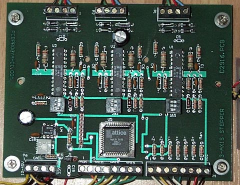
D2916: This is a 3-Axis Bipolar PWM controlled
stepper motor driver Board:
- 4 wire motors up to 0.75A per phase.
- 6 Wire motors up to 1.5A per phase.
- 8 Wire motors up to 0.75A per phase Parallel wired, or 1.5A per phase
for Serial Wired.

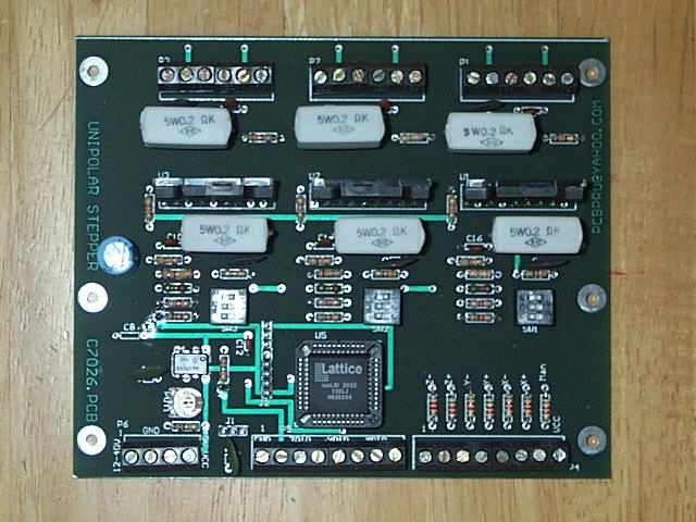
C7026: This is a 3-Axis Unipolar PWM controlled
stepper motor driver Board:
- 5 wire motors up to 3A per phase.
- 6 Wire motors up to 3A per phase.
- 8 Wire motors up to 3A per phase for Serial Wired.

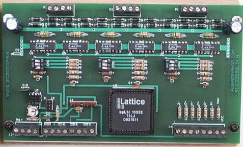
C3955: This is a 3-Axis Bipolar PWM controlled
stepper motor driver Board:
- 4 wire motors up to 1.5A per phase.
- 6 Wire motors up to 3A per phase.
- 8 Wire motors up to 1.5A per phase Parallel wired, or 3A for Serial
Wired.
