In-circuit 16F84 Programmers
Here are some simple ways of programming a 16F84 (or 16C84)
in-circuit. I was going to publish this stuff in Everyday
Practical Electronics as the hardware described here can
be used to upgrade their simple programmer. Unfortunately,
because they will be describing their own enhanced PIC programmer
suite called the PIC
Toolkit (to appear in the July 1998 issue) EPE weren't very
interested. Therefore, I've stopped working on the article but
here's what I'd put together before I packed up.
Programming "in-circuit" means the PIC is programmed
while installed in the project board (or "target board"
) under development. The target board supplies the PIC with power
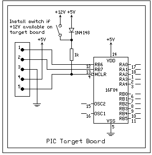
and has a connector that allows the programmer access to RB6,
RB7, /MCLR and +5V/VDD as shown below.
 |
The 1k resistor and diode ensure the PIC runs
normally when the programmer is not attached; they also
enable /MCLR to be controlled by the programmer - either
grounded or pulled up to around +12V to enter programming
mode. If you simply want to program a 16F84 you don't
even need these components and all the target board must
do in this case is supply the PIC with +5V. Otherwise,
apart from RB6 and RB7, all other PIC pins should be
connected as required by the project. The pins RB6 and
RB7 are reserved for use by the programmer hardware but
could be used by the target too under some circumstances.
|
The programming hardware is based on the quick-and-dirty
approach but the serial port versions are more conservative than
most in that they don't try to obtain the programming voltage
(VPP) from the serial port itself. The PIC can be connected
directly to the PC parallel or serial ports (via a couple of
resistors) or via simple interfaces for the parallel and serial
port I've called PARPIC and SERPIC respectively.
 |
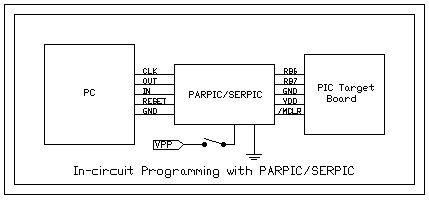
| The PC is connected to the programmer via four
logical signals called CLK, OUT, RESET and IN. Only the
CLK, OUT and GND connections are required but the
software will always control RESET and IN as well. The
hardware defines exactly which PC pins are used in the
programming process. VPP is applied by closing the switch
shown above however if a suitable voltage is available on
the target board the switch may be installed there
instead (see target schematic). |
 |
A direct connection from the serial or parallel port
needs virtually no hardware. All you need to do is run
the software and close/open the reset switch shown and
connect/disconnect VPP when asked. If a VPP supply is not
available on the target board an external source can be
connected to the programmer (perhaps a couple of 9V
batteries in series if the zener diode shown is fitted).
This scheme works pretty well but the only way to verify
the program has been downloaded correctly is to run it. |
 |
 |
| Adding a couple of transistors allows the PC to take
control of /MCLR and read the PIC contents via the
parallel port. This makes things a little more convenient
and enables the PIC contents to be verified. |
 |
 |
| A slightly different configuration makes it possible
to take control of /MCLR and read the PIC contents using
the serial port. This version also introduces inverting
buffers and steals VDD/+5V from the target so that the
signals on RB6/RB7 are guaranteed to be between 0 and
VDD. (A direct connection to the serial port relies on
the PIC protection diodes to keep RB6/RB7 within the
limits -0.6V and VDD+0.6V.) |
The software to go with the
programmers is based on PP V-0.5. So
far there is only very brief documentation
but there isn't much to say in any case.


