
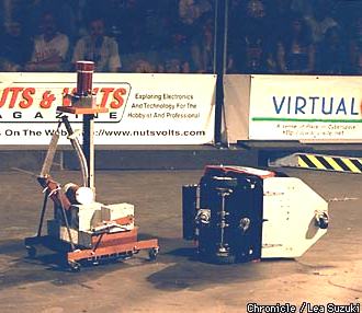
I've known Bob for several years. Heck, I used to work for him. Besides writing the rules and guidelines for the '97 Autonomous Class competition he designed and built the beacons for the event. He has been into robots for many years even going so far as to build a working R2D2. The nice thing about Bob is that he is always ready to lend a helping hand.
I suspect that if your here looking at this page you already know about Thumper. If you don't then you might want to check out the article about Robot Wars '97 at robotmag.com . Its a pretty good write-up and the author has some good tips on building a robot (RC or autonomous) for Robot Wars.
 Recently
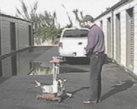
Bob invited me over to see and video tape Thumper in Action. Although
he had removed the flipper arm for some work the rest of the robot was
intact and functional. Bob took one of the IR beacons and then turned
it and Thumper on. Within about 5 seconds the robot had booted up
and locked on to the beacon Bob was carrying. Everywhere Bob went
Thumper followed. At one point Bob tried to hid the beacon behind
his back. Thumper went into a spin as it tried to find its target.
Suddenly it veered off toward a nearby building, the robot had detected
the reflection of the beacon off the wall. Oh, by the way, this took place
outside on a bright and sunny Saturday morning. The bright sunlight
didn't seem to bother Thumper at all.
|
 |
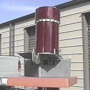 |
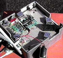
THE HEADThumper's "head" is about 6" square and about 4" thick. Inside this head is a Counterfeit Stamp from Scott Edwards Electronics, Inc. , 5 IR receiver modules, a handful of components and a 9 volt battery. Four mounting bolts protrude from the top of the brain box for the mounting of an IR beacon. Note the "eyebrows" shading the forward looking IR receivers from interference from sun light and video lights. |
| Inside the Head you can see the
two forward looking IR receivers, the two side/rear looking and the one
upward looking IR receiver (more about this latter). The piece of
black foam between the two forward looking receivers is to improve isolation
of the sensors.
You will note that the "brain" is powered by a single 9 volt battery. |
 |
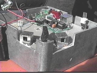 |
This is a front view of the two forward looking IR sensors. |
| The sensor in the back corner is situated so that it can look up at the beacon mounted on top of Thumper. By sampling the output of the beacon Thumper can tell the difference it's beacon and the beacon of its opponent. This also prevents Thumper from chasing the reflection of it's beacon and allows a certain degree of obstacle avoidance. | 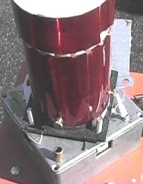 |
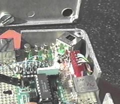 |
Interior view of the placement of the upward looking sensor. |
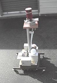
THE BODYMade from various pieces of scrap metal, Thumper's "body" is extremely rugged. It's most interesting features are the "arms" which serve a dual purpose. Armed with 6" stainless steel spikes the arms can damage or even overturn an opponent. In the event that Thumper is tipped over the arms automatically set Thumper back on it's feet. |
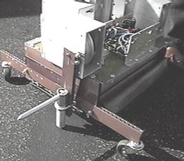 |
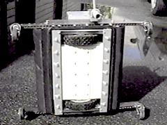 |
THE FEETThumper's "feet" are two 8" diameter wheels driven by two 12 volt DC motors. Each motor is controlled by a relay that is in turn controlled by the Counterfeit Stamp in the head. |
| This is the relay control box. the four white things at the bottom are 1 ohm 50 watt resisters that are used to dissipate excess current that would normally fry the motors if they should become overloaded. Like what happens when you try to push a robot twice your size | 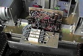 |
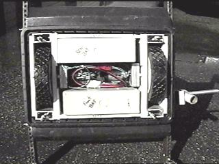 |
.This view shows the wheels, motors and two 12 volt Gel Cells that power the motors. The batteries are hooked up in series to supply 24 volts to the motors for increased speed. |
| And here's a view with the batteries removed. | 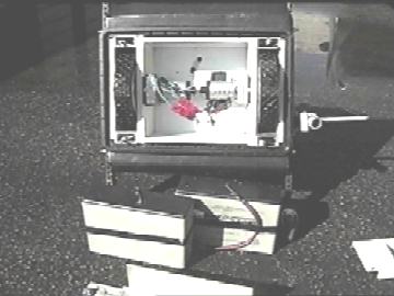 |
Go Here to look at the software Bob used
to run Thumper.
| Home Page | Links | Gaming |