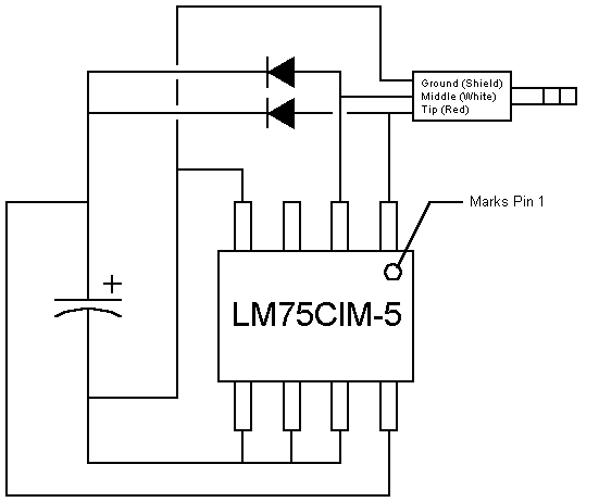
Thanks to Per Finander for the I2C routines.
--- INTRO ----------
The I2C Temperature Sensor is just like its name says: it is a temperature
sensor. It is a circuit that plugs into the link port of a TI-85, TI-83,
or TI-92 calculator and displays the temperature on the screen. Currently,
there is only software for the TI-85, but I plan to write some for the
TI-92 also. The sensor circuit draws power from the link port, so there
is no need for any external batteries. The overall size of the unit will
depend on the size you make it. Mine is about .75" by .5".
--- PARTS ----------
--- SCHEMATIC ----------
--- DIRECTIONS ----------
--- SOFTWARE ----------
The software, sensor.zip, I wrote to control the I2C Temperature Sensor is very simple to understand. Simply run the software and it will display the temperature on the screen in both Celcius and Farenheit. The software was written for use with ZShell 4.0 for the TI-85 calculator. For more information about ZShell and how to put in on your calculator, check out www.ticalc.org. If an error message appears on the screen, this section will help you. The program continuously updates the temperature about twice every second. To exit the program, simply press [EXIT]. There is also a feature that can be activated by pressing [F5]. This will allow you to change the chip ID that is set by the A0 to A2 pins on the IC. If this is set wrong, it will display an error on the screen. After pressing [F5], you can change the ID number by pressing [UP] and [DOWN]. Then, simply press [ENTER] and it will bring you back into the program. This also allows you to have up to 8 chips in the same circuit if you change around the circuit a little bit and give each one a separate chip ID set by the A0 to A2 pins. If changing the chip ID does not get rid of the error, make sure the plug is plugged into the calculator all of the way. If the error is still there, check over your construction of the circuit. If you have an error and change something external, either plugging in the cord or fixing something on the circuit, be sure to restart the program or alter the chip ID to restart the program.