SX28 Prototyping PCB

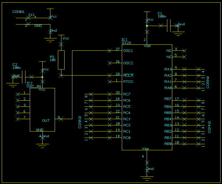
I designed this simple PCB for my own use. I've used a socketed crystal oscillator module instead of a ceramic resonator as I had a suitable 50 MHz module, and I might want to run the SX28 at 75 MHz. I've also provided a four-way Molex connector for in-system programming (ISP) using the Fluffy2 programmer. This was soldered into the prototyping area and wired up to the appropriate MCU pins. Ensure that you remove the oscillator module when programming the SX28 in-circuit, as the programming voltage will probably zap it if it is left in the socket.

The schematic above should be self-explanatory.

The PCB depicted above was designed for easy home production. It's single-sided with 15 mil tracks. The artwork for printing a transparency on a laser printer (I use an old HP LaserJet IIIp) is here.
Development tools I use for the SX28 are:
SASM assembler from Ubicom.
SASM_fix from here.
Fluffy2 programmer.
SXSim simulator from here.
Only use SASM_fix if you are using the simulator. It seems to screw up the hex file if you are using the Fluffy2 programmer.
Here is a simple test program for the board which toggles pin 11 of the SX28:
;test.asm
;simple test program for SX28
;toggles RB1 (pin 11)

fuse 	device	sx28ac,oschs1,turbo

	reset start

	rb	equ	$06

	org	$10
start:
	mov 	!rb,#0		;rb all outputs

loop:
 	call 	blink
	jmp 	loop


blink:
	mov 	W,#%0000_0010
	xor 	rb,W 		; toggle rb.1 (pin 11)
	ret