|
This Technical White Paper discusses Windows* related design issues and
compatibility requirements for modularized Audio Codec 97 (AC 97) subsystems
called the Audio/Modem Riser (AMR) or the Mobile Daughter Card (MDC).
Intel provides the AC 97 specification for adding analog codecs to a
system board chipset, and a specification for AMR. There is diversity
in system board chipsets and codecs that will support AC 97, and in AMR
or MDC subsystems that use these codecs. Ensuring that the correct drivers
are loaded is a significant issue. AMR was not designed for use as an
add-in card. However, it can be used like one. PC manufacturers must be
aware of the potential for problems if they do not exercise strict controls
over system configurations. An AMR board must be used with a specific
system board and BIOS. The Audio/Modem Riser is supported by utilizing
the Plug and Play system design methodology. The AC 97 codecs on an AMR
device are attached to the system board chipset, which is exposed as a
PCI bus device. One of the solutions outlined below must be used to present
unique subsystem IDs and device IDs on the PCI bus for the combination
of system board chipset, BIOS, and AC 97 device(s) in order to support
Plug and Play for Windows. 2. AC 97 ID Space The PCI specification allows
for two 16 -bit sets of Vendor Specific IDs. The BIOS must read the codecs
VID1 and VID2 and use them as reference into a lookup table to determine:
1. Subsystem Vendor ID (number assigned to the AMR or baseboard manufacturer
by the PCI SIG) and 2. Subsystem ID (AMR and/or codec device ID) The Subsystem
Vendor ID (SSVID) and Subsystem ID (SSID) must be programmed for proper
device driver enumeration and loading. For the audio function, programming
the codec VID2 value into the Subsystem ID register is sufficient to fulfill
step 2, above. However, for modem riser SKUs the codec ID is not sufficient
and the OEM must provide a unique identification number for the Subsystem
ID. Reg Name D15 D14 D13 D12 D11 D10 D9 D8 D7 D6 D5 D4 D3 D2 D1 D0 Default
7Ch Vendor ID1 F7 F6 F5 F4 F3 F2 F1 F0 S7 S6 S5 S4 S3 S2 S1 S0 na 7Eh
Vendor ID2 T7 T6 T5 T4 T3 T2 T1 T0 REV7 REV6 REV5 REV4 REV3 REV2 REV1
REV0 na Table 1: Codec Vendor ID registers 2.1. Mechanisms to accomplish
a modem riser enumeration The following addresses the basic Plug and Play
(PnP) requirements for AMR modem implementations. Two alternative solutions
are provided, using BIOS Fail Safe Mode, and using serial EPROM or shift-register.
The key features of each are outlined.
R Page 3 The essential issue for the OEM and AMR vendor is to provide
a unique identification (AMR Model No.) of the baseboard and AMR combination.
Model information for AMR devices is available from the AMR vendor. However,
this information is not readily available to the BIOS to correctly program
the PCI Modem function of the core logic chipset. Given that the AMR is
added during the final stages of manufacturing, the BIOS does not know
which AMR is installed on the baseboard. 2.1.1. Use BIOS Fail Safe Mode
One possible solution is to provide a BIOS setup option that is accessible
only during the manufacturing process or during the Fail Safe recovery
process. A setup option for the AMR ID will allow the manufacturing operator
to enter the unique ID of the AMR module that has been stuffed in the
baseboard. The ID can be retrieved from AMR PCB silkscreen or a similar
mechanism. This ID number would then be used by the BIOS, during the AC
97 identification, to program the SSID field of the core logic chipset
PCI AC 97 Modem Function. The PCI modem function can load a driver that
is uniquely identified for the AMR device, when the unique AMR ID is programmed
in the SSID and the OEM or AMR vendor ID provides the information for
the SSVID. Key Features of this proposal · Fail Safe BIOS is available
only during Manufacturing or by changing a jumper on the baseboard · User
cannot change the AMR ID accidentally · The AMR is uniquely identified
· Driver can properly load based on the SSVID and SSID information · OEM
requires a manufacturing step change/addition · BIOS must add a new setup
option · OEM software must be modified to configure OEM flash space (for
AMR ID additional information) 2.1.2. Use Serial EPROM or Shift-Register
AC 97 Modem Codecs today provide a number of GPIO pins in order to control
external logic. A pair of these GPIO pins can be used to clock-in a unique
ID from an external serial EPROM or Shift register. After the clocking
procedure, the BIOS performs a modified AC 97 identification process,
to program the SSVID and SSID registers of the core logic chipset modem
function. Using the unique SSVID and SSID the PCI modem function can load
a driver that is uniquely identified for the AMR installed in the system.
The following figure displays a possible diagram of this implementation:
R Page 4 Figure 1: EPROM Diagram
Key Features of this proposal
· User cannot change the AMR ID accidentally
· The AMR is uniquely identified
· Driver can properly load based on the SSVID and SSID information
· BIOS is required to add a new identification algorithm
· AMR cost is increased by added logic
· Current AMRs may not use this methodology
· Most modem codec vendors must modify their devices to address this
proposal
Pri. Codec SYNC BIT_CLK SDATA_OUT AMC/MC'97 Digital AC '97 Controller
inside ICH RESET# SDATA_IN_0 S-EPROM GPIy Clock Data GPOx
|

 The
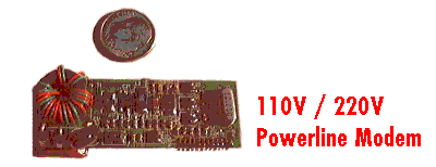
AMR Tech P2 NODE SIP Network Interface module is a highly integrated advanced
spectrum communication transceiver and channel access interface for implementing
low-cost networking products. The P2 NODE SIP provides the Data Link Layer
(DLL) control logic for channel access using unacknowledged services, a
Spread Spectrum Carrier (SSC) transceiver, signal conditioning circuitry,
and an SPI compatible host interface. A minimum of external circuitry is
required to connect the P2 NODE SIP to the AC power line, a twisted pair
cable, or other communication medium. The P2 NODE SIP is used with a host
microcontroller to construct simple sensor and actuator devices for use
in lighting control, process monitoring, access control, point-of-sale,
telemetry and other systems requiring low-cost network capability.