The manufacture of printed circuit boards begins with the fabrication of the bare board itself, starting with one or more bare sheets of copper-fiberglass laminate. The first step in processing the laminate is to drill the holes for component leads and circuit vias. This drilling is typically performed on a CNC-controlled drill machine, using a program generated from the original design data by a computerized design system.
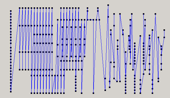
Here is an example layout for the holes to be drilled in a printed circuit board. (This design actually calls for several different sizes of holes to be drilled, only one of these hole sizes is shown here for simplicity' sake.)

The drill program generated for this board follows a zig-zag path, tracing back and forth across the circuit board. If you look closely, you can see that this path corresponds with a simple sort of the hole coordinates, first in the X-direction, and then in the Y-direction. This path will cause the drill machine to scan from side to side over the surface of the board.
As it turns out, this is a reasonable first-pass tool path, but it is far from optimal.
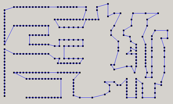
This figure shows the same drill program, but this time after having been optimized to reduce the tool path. In this example 80% of the tool travel has been eliminated, simply by reordering the drilling sequence.

In PCB drilling, 25-40% of the processing time is spent in tool movement, 3-5% is tool changes, and the remainder is the actual drilling process. The number and sizes of holes are dictated by the board design itself, and so we are stuck with this amount of processing time. However, the board design is unaffected by the order in which the holes are drilled. Tool path optimization typically reduces tool travel 30-50%, and in some cases up to 80% and more.
If the tool path reduction is conservatively estimated at 50%, and the contribution of tool travel to processing time is similarly estimated at 30%, you can see that by simply reordering the hole drilling sequence, you can gain a 15% capacity increase, with NO CAPITAL EXPENDITURE and NO NEW EQUIPMENT! Combine this with the common case in which drilling is the bottleneck operation of a circuit board fabrication facility, and this can translate into a significant increase in factory capacity.
Manual optimization is subject to human speeds, and human error. Manual sequencing of drilled holes can be time-consuming for all but the simplest drill programs. It is also easy to introduce program errors when modifying them by hand.
In addition, computer optimization is able to find shorter tool paths, counter to what would seem to be "common sense." The human eye can be fooled into working with groups of holes, when an optimal path may involve breaking up some of these groups (see example, lower left corner).
Identify those circuit boards in your production schedule that account for the most capacity consumed. These will most likely be the boards that are run in the highest quantity per month (although lesser volume boards may use more capacity if they are especially complex, with many holes to be drilled). Select the top 2 or 3 designs, and optimize their drill programs. Measure the time to drill a board using both the original, unoptimized drill program, and the optimized drill program.
Drill program optimization can be initially tried on high-volume designs; this will maximize the leverage of the high runners to get most production capacity return from early program adjustment.
Should monitor drill accuracy and maintenance schedule, as optimized drill programs may induce greater load on lead screw thrust bearings, due to more frequent direction changes.
Also look at additional throughput enhancing methods, such as the use of higher-grade drills and entry material to enable faster plunge speeds, reducing the time required to drill holes without sacrificing hole location accuracy and finish quality. While these measures may involve additional expense for consumable material, they can pay for themselves in increased throughput and product quality.
Finally, establish tool path optimization as part of the regular process of releasing design data to manufacturing. This way, your manufacturing program repository will continue to run in an optimized mode, even as new designs come along to replace the current ones.
Other processes which could benefit from this simple step include surface mount glue and solder paste dispense, component pick-and-place, and sheet metal punching.
Click here to see more examples.
You can send me a sample drill program to optimize for free, using my beta test software for drill program optimization. Go to "Submit Drill Program for Free Optimization".
For more information, please contact me at
ptmcg
@
austin
.
rr
.
com.