For more information on Intel HEX file formats see Microchip document DS91026A.
Compiling the source code
FreePicProg was developed using VisualC++ 6.0 No special header files or libraries are needed to compile the source. (You may also be able to compile the source with VisualC++ Express. VisualC++ Express is available free from Microsoft.)Getting started using the SimplePicProg in circuit programmer
- Connect the programmer to the parallel port (plug the DB25 adapter directly into the parallel port)
- Type 'fpp' - this will display the format of the command line arguments.
- Type 'fpp lvp -t' - this will check if the software can communicate with the programmer
- Connect the programmer to the PIC circuit
- Apply power to the PIC circuit
- Type 'fpp lvp device_name -i' to display the device id of the chip. The command
should succeed without any error messages.
- You are now ready to use the programmer.
The software has two different options for the SimplePicProg programmer: "lvp" and "lvp_fast". The latter uses shorter clock cycles and may be used with cables less than 2 meters in length.
With the SimplePicProg programmer your circuit must be designed to accommodate the programmer:
- The MCLR/VPP pin should be pulled up to Vdd with 39K
- The LVP/PGM pin should be grounded with 120K
- Construct the filter circuit on PGMCLK and PGMDATA as shown on the circuit diagram.
- You may use the PGMCLK and PGMDATA pins in your circuit, however the load resistance on these pins cannot be less than 270K. (The load resistance cannot be significanly higher than 270k either because the leakage current of the PIC inputs.) With the 18f452 you should dedicate the PGMCLK and PGMDATA pins to the programmer if possible.
- The voltage supply of the PIC chip must be between 4.75 and 5.25 volts
- Do not forget to bypass the power supply with a 0.1uF ceramic capacitor. Place the bypass capacitor as close to the chip as possible.
Getting started using the P16PRO40 programmer
- Connect the P16PRO40 programmer to the parallel port, make sure the programming socket is empty.
- Apply power to the programmer.
- Type 'fpp' - this will display the format of the command line arguments.
- Type 'fpp p16pro40 -t' - this should succeed and both the red lights on the programmer should be now off.
- Insert the chip into the programmer.
- Type 'fpp p16pro40 device_name -i' to display the device id of the chip. The command should succeed without any error messages. (The 12f675 has no device id, if you are using the 12f675 skip this step.)
- You are now ready to use the programmer.
When using the P16PRO40 always remember the following:
- Insert the chip into the programming socket only when the green led is on and both red leds are off.
- Remove the chip immediately after programming. Do not turn off the computer while the P16PRO40 is turned on and a chip is in the programming socket.
The SimplePicProg programmer
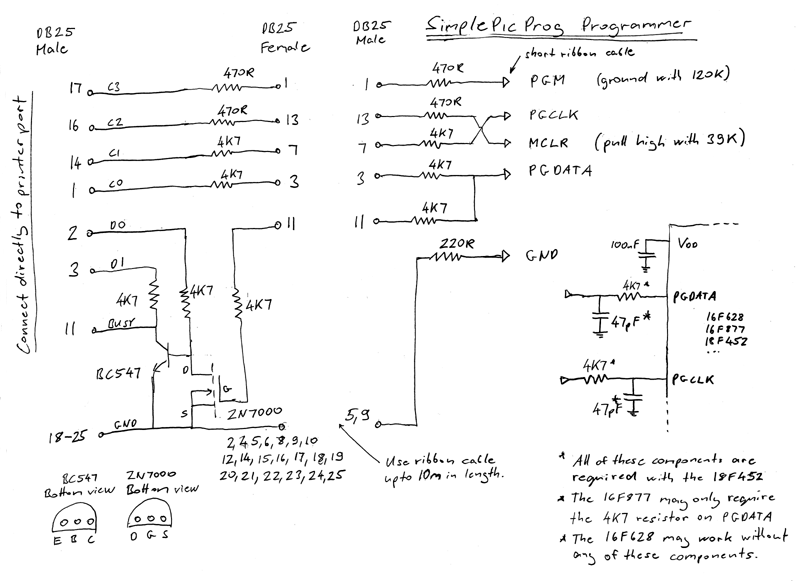
The parallel port outputs C0 to C3 are open collector outputs pulled to +5V with 4K7 resistors. The series resistors on the output lines provide protection to the computer and limit transients.The PIC device's programming pins (PGM, MCLR, PGCLK, and PGDATA) have schmitt trigger inputs. The maximum low input voltage on these pins is 0.2 VDD (1V) and the minimum high input voltage is 0.8VDD (4V). The open collector outputs of the parallel port satisfy these requirements.
The PC parallel port inputs are TTL level compatible. TTL inputs have a maximum rise time of about 1us. The series resistors together with the cable capacitance create rise times that well exceed this limit. The 2n7000 logic level mosfet and the BC547 transitor is used to increase the rise time of the input to TTL specifications.
The 220R resistor on the ground line provides protection to the computer by limiting current flow.
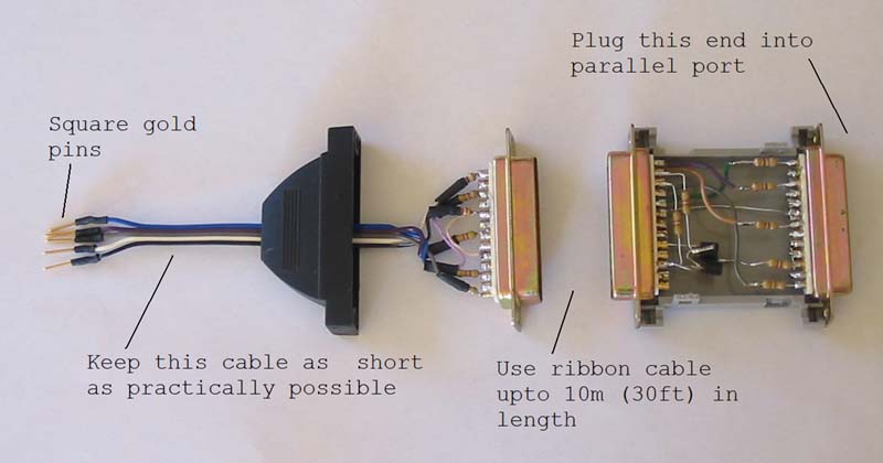
It is essential to connect all ground lines as shown on the circuit diagram. It is also essential that you use a ribbon printer to connect the programmer.
The internals of SimplePicProg

SimplePicProg circuit diagram

Known problems
Programming may fail intermittently under Windows XPProgramming may fail intermittently under Windows XP with the following error message: "Error while writing to the parallel port: ..." This may be caused by Windows trying to access the parallel port while the programmer is active. This problem appears to be dependent on how Windows XP is configured. On some computers this never occurs; on others it happens frequently.
Here is a list of suggestions that may help:
- The following registry entry will stop Windows XP checking for new printer connections:
[HKEY_LOCAL_MACHINE\SYSTEM\ControlSet001\Services\Parport\Parameters] "DisableWarmPoll"=dword:00000001 - Try disabling the Windows parallel port device driver. On some computers this may make the
parallel port inaccessible.
- Disable the parallel port on the motherboard and install an old non plug and play parallel port ISA card. Disable the Windows parallel port device driver. This will only work on older computers with ISA slots.
Any software that bypasses the Windows parallel port driver and writes to the parallel port directly is likely to suffer from the same problem. At this time I know of no other parallel port PIC programming software that runs under Windows XP and uses a proper parallel port device driver.
When using the SimplePicProg in circuit programmer, programming or verifying may fail occasionally with the 18f series chips.
I haven't been able to reliably reproduce this problem. If you find a solution to this problem, please contact me.
Web links
- Microchip
- The manufacturer of the PIC microcontrollers.
- Pic Book
- Lots of information on the 18F452. There is also a free PIC Programmer software
that can program a 18F452 using the P16PRO40 programmer.
- Dontronics
- The P16PRO40 is available from Dontronics for about $US20.
- Scientific Software Tools
- You can download the DriverLINX DLPortIO from here.
- WinPicProg
- A free PIC programmer with a graphical user interface
- www.picallw.com
- Commercial PIC programmer software for the P16PRO40.
You can also find the circuit diagram for the P16PRO40 programmer here.
- PiKdev
- Open source development environment and programmer. Runs under Linux.

Last updated 12 September 2004
