Larkin's thermosyphon solar air heater


David M. Delaney
October 30, 2007
larkin-tap-1.GIF
Larkin's solar air heater heater, US Patent 4,519,383, 1985,  operates entirely passively (no fans) by natural convection (thermosyphon).  Most solar air heaters need one or more dampers -- one-way air valves that prevent a reverse flow of air that would otherwise cool the building at night as rapidly as it was heated during the day. Larkin's solar air heater, shown to the right,  has neither dampers nor any other moving parts. It  uses buoyancy principles to prevent reverse flow when there is no sun.

During the day, the sun heats a solar absorber in the  heating chamber (HC). The solar absorber heats the air of the HC, making the column of air in the HC less dense than the room air. The air in the riser duct (RD) and descender duct (DD) have substantially the same temperature and same density as the room air.  The columns of air in the RD and DD form a syphon which impedes the motion of air through it only by the effects of friction and turbulence produced in the moving air, not by a net opposing pressure difference due to density differences.  The substantial difference of density between the air in the HC and the air  in the room drives a flow of air through the heater, as shown, heating the room.

At the end of the day, the air in the HC becomes substantially colder and more dense than the air in the room. As the sun disappears, the air flow slows, then stops, then begins to move slowly in the reverse direction.  The air in the HC flows slowly into the DD until the temperature and density of the air in the DD and in the HC are approximately equal.  During the cooling of the air in the HC, and the slowing, stopping, and reversal of air movement, the low opening between the room and the RD keeps the air in the RD at substantially the temperature and density of the warm air in the room.  We can view the system of the room and heater as two same-size U tubes, one U tube formed by the room and the RD, the other U tube formed by the DD and the HC.  The two U tubes are joined at the top of one leg of each U, the other leg of each U opening to a shared atmosphere at the same pressure and density.  The air volumes in each of the two U tubes have distinctly different temperatures and densities, and different pressures at their bottom ends, but the air volume within each U tube is relatively homogeneous in temperature and density, and there is no difference of pressure between the open ends of the two U's. There is, in other words,  no resultant pressure difference to drive a flow of air.  The air in the U tubes becomes essentially motionless relative to its rapid movement when the HC is being heated by the sun..

There will be a slow night-time reverse flow because of  heating of the DD by conduction through the partition separating the DD from the RD, the RD air being at approximately the much warmer temperature of the room air, while the DD air is at approximately the temperature of the outdoors. This heat flow warms the air in the DD making it less dense than the air in the HC, disturbing the balance between the DD and the HC, and producing a slow reverse flow.  This heating of the DD by the RD can be greatly reduced by raising the thermal resistance of the partition that separates the RD from the DD.  The night time thermal resistance of the whole area of the air heater to heat flow from the room to the outdoors  is approximately equal to the sum of the thermal resistance of the glazing and the thermal resistance of the partition between the RD and the DD. The other two partitions -- the partition between the room and the RD, and the partition between the HC and DD -- are essentially insignificant from a night-time heat transfer perspective, because of the ease with which convection moves energy between the volumes separated by them.

During the day,  heating of the air in the DD by conduction through the partition separating the HC and DD can slow the air flow by reducing the density of the air in the DD.   This effect can be neglected if the power of the heat flow from the HC through into the DD is at most a tenth, say, of the power of heating of the air in the HC.  Providing a separate solar absorber suspended in the middle of the HC will keep the sun from directly heating the partition.

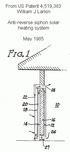
For very high night-time thermal resistance, as for a super-insulated house designed to have no back-up heat source and a large internal thermal mass possibly provided by phase change material lying above steel ceilings,  it seems appropriate to split the air heater into an RD affixed to the interior of the high-performance wall of the superinsulated house, and a combined DD and HC affixed to the exterior of that wall. The partition between the RD and DD would be provided by the superinsulated wall of the house. (See Fig. 1 of Larkin's patent, below.) This configuration would achieve a night-time thermal resistance over most of the area of the air heater equal to the thermal resistance of the superinsulated wall, in parallel with the thermal resistance of the glazing over the area of the opening through the wall provided for the passages between the room and the HC and between the RD and the DD.

The night-time thermal resistance of the whole air heater having could be made equal to that of the high resistance partition by replacing  the glazing with insulation from the top of the glazing area shown above down to the level of the top of the partition between the RD and DD. Larkin shows, or hints at,  such insulation in Fig. 1 of his 1985 patent, below.  The light admitted to the room through uninsulated glazing in front of the opening to the room can be quite valuable, however.

Larkin's patent

William J. Larkin patented his anti-reverse siphon solar heating system in 1985 in US Patent 4,519,383. See Fig. 1 of the patent, and the excerpt below from the section of the patent titled, Detailed Description of the Preferred Embodiments. See also claim 1 of the patent.  The patent has expired.

Excerpt from Larkin's 1985 patent:


Larkin-Fig-1-US-Patent-4519383.gifThe essence of the invention is shown in FIG. 1. In order for the heater to work properly, there need be a fluid mass, which in FIG. 1 is the air in the room 10, and a fluid flow passageway comprises an ascending passageway 12 which loops over into a descending passageway 14 which is separated from the ascending passageway by means of an insulator 16, which in the embodiment of FIG. 1 takes the form of an insulated wall. At the bottom of the descending passageway, the continuous passageway flows into a heating chamber 18 in which the fluid is warmed by means of heating element 20. In this embodiment, the heating element is a flat plate absorber, which defines the heating chamber together with glazing 22.

As the sun passes through the glazing and into the absorber, air in the heating chamber 18 expands and circulates out through the upper outlet 24 while drawing fresh air into the inlet 26.

At night, the absorber will dissipate heat through the glazing and become the coldest part of the system. The heating chamber 18 will become a cooling chamber, and as the density of air in the heating chamber increases, it will develop a pressure head and try to move downward. Ordinarily, if the bottom of the heating chamber entered directly into the room, there would be a constant, steady flow of cold air back into the room, while hot air would be drawn out of the room at the top through what was supposed to be the warm air outlet 24. With this system, however, as the cold air moves downwardly and forces warmer air up the descending passageway 14, because of the insulation 16, cold air fills the descending passageway as well as the heating chamber, equalizing the pressure head. Backflow is thus eliminated.

It is not always desirable to prevent backflow. When it is cool outside and the house is hot, backflow would be desirable. Or, if the unit faces north, it could effectively be made to backflow even in the daytime through use of the butterfly valve 27. As illustrated in FIGS. 2 and 3, when this valve is open, the anti-reverse-siphon feature is completely negated and reverse siphoning takes place as though the loop had not been incorporated in the first place.

I suspect that many people have considered implementing this configuration, but have judged without implementing it that  the probability was too high that the resistance to air flow caused by the long ducts and the numerous changes of direction of  flow it requires -- six 90 degree turns -- might overwhelm the driving force provided by the density differences,  making the heater inefficient. It is not clear that this is so, and efficiency isn't everything. An entirely passive air heater with no moving parts could have outstanding reliability and durability. Morris Dovey's company, DeSoto Solar, has built and sold a solar air heater that uses the principle of Larkin's configuration.  According to his reports and the existence of his customers, it seems to work very well.

Home


1