Adding a chock to the camera support system
September 15, 2008
Experience showed that the camera support system described in Simple inexpensive tabletop camera support
was too simple. The vise had to be tightened inconveniently hard.
There was also a risk of the beam (and camera!) falling when the vise
was
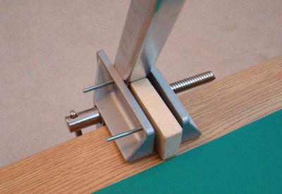
loosened to adjust the beam angle. A chock was added as shown
below to support the beam in the vise, so that the vise needs to
be tightened only sufficiently to eliminate wiggling of the beam.
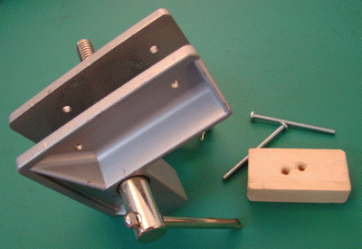
The chock is a piece of wood, 3" x
1-1/2" x 3/4". Two 3/16" diameter carriage bolts pass through the jaws
of the vise to pin the camera support beam and the chock to the vise.
The bolts need no nuts. They are held firmly in place by the loads they
support, and need to be easy to remove and replace to adjust the beam
angle. The holes in the vise jaws were provided by the manufacturer of
the vise to facilitate the attachment of wood facets to the
jaws. The two holes in the chock provide four angles of
beam elevation of which two are not very different , so there are three
usefully distinct angles of beam elevation with the chock installed,
and the horizontal position of the beam with the chock removed.


Back to Simple inexpensive tabletop camera support
Home

