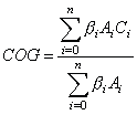
where n is the number of rules applied to the particular output.
Project Paper
Fuzzy Expert System for Navigation Control
By
Koay Kah Hoe (B. Eng.)
Microelectronic and Computer Engineering Department (MiCE)
Faculty of Electrical Engineering
University of Technology Malaysia
1998
Abstract
The fuzzy logic technology can be implemented in pure software, pure hardware or combination of both. A combination solution, which is called fuzzy processor, is implemented using Intel microcontroller 87C251SB and Xilinx FPGA XC4003EPC84. The microcontroller is the core of the fuzzy control system. Additional fuzzy processing element provides parts of fuzzy operations in hardware implemented on the FPGA chip. The fuzzy processor is designed to be general purpose, stand alone and featured with analog inputs and analog outputs. The fuzzy knowledge base is stored in non-volatile memory and can be reprogrammed through serial interface with PC.
The fuzzy expert system developed is applied to a golf cart navigation control problem, where a golf cart is navigated automatically avoiding obstacles towards a selected destination in a golf course. This is a known-environment navigation problem, which provide an adequate test framework. The problem is simulated on a PC and the fuzzy processing is performed in the fuzzy processor through a serial connection. A user interface is created to define and develop the fuzzy knowledge base, then downloaded to a non-volatile memory. The fuzzy processor receives five input variables, namely the distance to obstacle, the angle to obstacle, the distance to destination, the angle to destination, and the speed of the cart. The distances and angles are referred from the golf cart. The output variables are acceleration and steering angle of the golf cart. Further research is carried out to further improve the system performance and apply the fuzzy expert system in a real-time navigation control in a maze environment.
Introduction
Fuzzy logic technology is one of the AI (Artificial Intelligence) techniques first developed by Lotfi Zadeh in 1965. This technology solves control problems in fuzziness and linguistic way. Fuzzy logic has rapidly become one of the most successful of today's technologies for developing sophisticated control systems. With its aid, complex requirements may be implemented in amazingly simple, easy maintained and inexpensive controllers. Fuzzy logic has been successfully applied to a large number of diverse applications such as nuclear reactor control, ship crane control, subway system control, chemical process control, domestic appliances and navigation control.
Implementation of Fuzzy Logic
There are a number of ways to implement the fuzzy logic. Generally, we can divide them into two broad categories, i.e.,
Table 1 shows the fuzzy system implementations for standard hardware and fuzzy hardware. Fuzzy algorithms are usually implemented on standard hardware. However, if the system to be controlled or classified is complex and demands many fuzzy rules, or if it is fast and demands high-performance real-time processing, fuzzy hardware is required.
| Standard Hardware | Fuzzy Hardware |
|
|
In this project, a combination of hardware and software solution of fuzzy logic is implemented using a standard microcontroller and external fuzzy add-ons providing fuzzy functions. The microcontroller used is 87C251SB from Intel and the fuzzy add-ons are implemented on XC4003EPC84, an FPGA from Xilinx. This implementation is closer to category FP (Fuzzy Processor), although microcontroller is used instead of microprocessor, and the add-ons are provided externally. The fuzzy processor is designed to be general purpose, stand alone and featured with analog inputs and analog outputs.
System Overview
The fuzzy expert system was applied in a golf cart navigation control, where a golf cart is navigated automatically avoiding obstacles towards a selected destination in a golf course. This is a known-environment navigation problem, which provide an adequate test framework. The fuzzy expert system consists of three main parts:
Figure 1 is a block diagram describing the interconnections among each part of the system.

Fuzzy Processor Components
The hardware components of the fuzzy processor contain two main parts: a fuzzy processor board and an FPGA board. Inside the fuzzy processor board, it contains the microcontroller as the core of the fuzzy processor board, serial interface for interfacing with the PC, A/D converter and D/A converter for analog inputs and analog outputs respectively, and non-volatile memory for storing fuzzy knowledge base. The FPGA board has fuzzy processing element and memory decoder. The fuzzy processing element provides hardware circuitry that computes fuzzy operations while the memory decoder partitions the memory usage for different devices. The functions of some parts of the hardware will be discussed below:
Implemented Fuzzy Algorithm
This section reviews the fuzzy logic algorithm employed in this project. Most of control applications of fuzzy logic can be generalized by means of a simple structure shown in figure 2. Generally, a fuzzy logic controller consists of four main components:
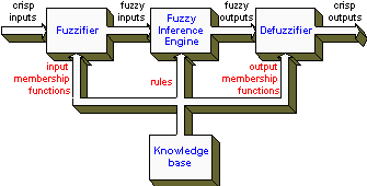
Fuzzifier converts the crisp inputs to fuzzy inputs. The fuzzy inputs are used in the inference engine to generate fuzzy outputs. Then, the fuzzy outputs are fed in the defuzzifier to generate crisp outputs. The knowledge base provides input membership functions to the fuzzifier, rule-base to the inference engine, and output membership functions to the defuzzifier. These are the settings needed by a fuzzy logic controller in order to get the proper output control signals.
The fuzzy algorithm used in this project is modified from conventional fuzzy algorithms to optimize the system performance by reducing computation operations needed. The following subsections describe each component of the fuzzy logic controller.
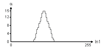
The input membership functions are defined in a look-up table based method. The universe of discourse of the input variables is limited to one byte length, ranges from 0 to 255. The resolution of membership grade (denoted by a ) is 4 bit wide, ranges from 0 to 15. Thus, the value of input variables must be normalized to one byte wide before running fuzzification process. Figure 3 shows an example of one input membership function defined in the look-up table. It takes 256 bytes to record one membership function in knowledge base memory (KBM). Although the value of a changes quite discretely, it is still acceptable, as fuzzy values do not require being too precise.
The fuzzy inference used is simple. To record rules in KBM, for each rule, the membership of each input is stated and the corresponding required output membership is also stated. For example, say there is a system of 3 inputs and 2 outputs, one of the rules are as below:
If In1 is NM and In2 is PS, then Out1 is PM.
In the knowledge base, it is recorded as follow:
[In1NM] [In2PS] 00 00 [Out1PM]
where
| [In1NM] | = 2-byte offset address of where the NM membership of input 1 is defined. |
| [In2PS] | = 2-byte offset address of where the PS membership of input 2 is defined. |
| 00 00 | = Denotes that input 3 is don't care. |
| [Out1PM] | = 2-byte offset address of where the PM membership of output 1 is defined. |
The offset addresses are used to point to membership functions instead of using indexed number. Thus, there is no further calculation needed to locate the address where the memberships are recorded. This method reduces computation time in fuzzy inference process. Rules for different outputs are defined separately.
The value of each crisp input will be added to the given offset address to get a of that input. Then, the minimum (denoted by b ) among the a values from the inputs is calculated. b will be used in defuzzification process.
The defuzzification process is using COG (Center Of Gravity) method. The output membership functions are defined in rectangular shapes only. This is to reduce computations needed to get the crisp outputs. An example of the output membership function is shown in figure 4. In the figure, A is the relative area factor of the rectangular and C is the center point of the rectangular. A is 4 bit wide and C is one byte wide. To compute the crisp output, apply the COG formula as follows:

where n is the number of rules applied to the particular output.
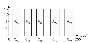
The values of C and A are recorded sequentially in KBM for each output membership function. In the fuzzy inference rule base, the 2-byte offset address for the output membership function, which is [Out1PM] in the last example, is pointed to C and A.
Figure 5 shows the memory map of KBM. In this map, the address increases from top to bottom. From left to right, the map items are shown from the biggest group division to the smallest item details hierarchically. The rightmost column shows the memory space needed to store the data at the corresponding rows.

The first and second byte of the memory stores the number of input variables and the number of output variables respectively. These values are very important in calculating the loop counts in the fuzzy algorithm. Then, the number of rules for each output is defined sequentially. Note that the fuzzy rules are defined separately for each output. The following byte is not used and set to FFh, it is reserved for future use. The following parts are the actual fuzzy rule base definition. They are fuzzy rule table, input membership function table and output membership function table.
This memory organization creates flexibility for the user. The number of rules for each output can be up to 255. The number of memberships for inputs and outputs is not stated in the memory and can be defined freely by user, as the rule table will directly point to the offset address of the membership function.
Fuzzy Algorithm Program flow
Figure 6 is a graphical illustration showing how the fuzzy algorithm works. The tables in the illustration are read from knowledge base memory. The program will read the first rule from the rule table. In this case, input 1 points to MFx in the input membership function table. The crisp input 1 will be added to the offset address to point to the corresponding grade a1. This value is then sent to the beta generator, which is implemented in hardware. Similar to the input 1, input 2 follows the same procedure to get a2 and the value is also sent to the beta generator to generate the minimum among a values, namely b . The beta generator must be reset for each rule.

The next step is to get output membership function. From the rule table, MFz points to the output membership function table to get C and A. C, A and b are multiplied and accumulated at SC*A*b block. While A and b are multiplied and accumulated at SA*B block. After accumulation process, one rule is completed. The program will proceed to the next rule repeating the same procedures. After completing all the rules for an output, the divider will be activated to compute the desired crisp output. The accumulator blocks will be reset to zero for a new output.
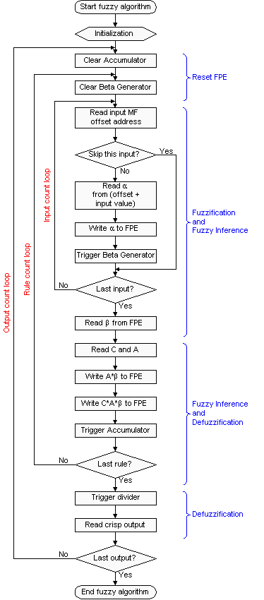
Figure 7 shows the flow chart for the fuzzy algorithm. Note that, there are three loops in the flow chart. The innermost loop is the input count loop, which counts the number of inputs, as each rule will access membership for each input. There are cases when certain input is not used in a certain rule, the offset address is recorded as 0000. When the program encounters a zero offset address, it will proceed to the next input. This is done at the decision block "Skip this input?". The second loop is rule count loop, the program process the rules one by one in the rule count loop. The outermost loop is output count loop, the program computes outputs sequentially.
Knowledge Base Development
The fuzzy knowledge base, or known as fuzzy inference system in Matlab, including definitions of input membership functions, output membership functions, and fuzzy rules, is created using the Matlab's Fuzzy Logic Toolbox. The software provides a handy GUI environment for the user to design, simulate and verify the fuzzy control system. User can integrate the inference system that is created from this toolbox with other toolbox. The fuzzy inference system can be easily tested and simulated in a block diagram based simulation environment using the Simulink simulation tool. Non-real time code or real time code can be generated using the Real Time Workshop.
In this project, the Fuzzy Logic Toolbox is used to generate the fuzzy inference system and then a conversion program is used to export the data to a specific format which is recognized by the golf cart navigation simulator program.
Golf Cart Navigation Model
The navigation model is very important to create a successful navigation control. It is assumed that in the golf cart navigation, the environment is known. It means that the locations of the golf cart, the targeted destination and all obstacles in the golf course are known exactly. Also, obstacles like trees in the field are assumed as point objects. Thus, all objects in the problem are basically point objects, including the golf cart, obstacles and destination. Adequate input and output variables are required to model the environment and control the golf cart. 5 input variables and 2 output variables were identified, as follow:
Input variables
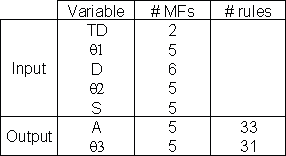
The distances and angles are referred from the golf cart. The cart navigation geometry is illustrated in figure 8. Based on these variables, fuzzy membership functions can be defined for each input variable and output variable, and the fuzzy rules can be set in Matlab Fuzzy Toolbox. Table 2 shows the number of membership functions defined for each variable and number of rules used for each output variable.

Navigation Simulator Program
A golf cart navigation simulator program was written in Visual Basic to simulate the golf cart navigation. The program provides a GUI environment for the user to:
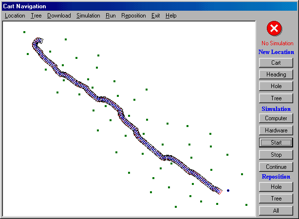
When simulating the navigation, the program displays the golf cart movement on screen. The program leaves the trail undeleted for the user to see the path taken by the golf cart. The user can choose either to simulate the navigation by using computer only or using the fuzzy processor. The user can compare the result achieved from these two simulations. When using hardware simulation, fuzzy input variables are sent to the fuzzy processor through serial interface. The fuzzy processor will then carry out fuzzy algorithm to get outputs needed. The outputs are then sent back to the computer.
Results
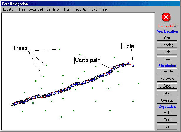
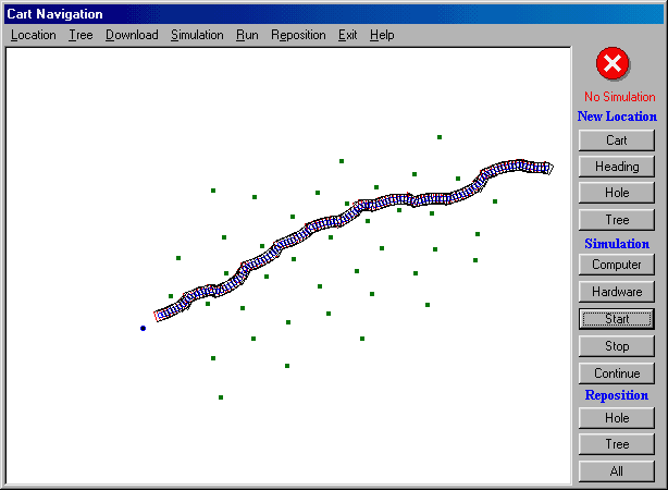
A series of simulations were carried out on different situations, the results are satisfying. The following figures show several examples of results captured from computer screen. In figure 9(a), the golf cart navigates from southwest towards the hole (destination) at east side of the field leaving its path undeleted. The destination is represented by a deeper dot, and other dots represent trees or obstacles. Figure 9(b) and 9(c) shows another two examples, which have more obstacles along the navigation path. Figure 9(c) shows that at the beginning of the navigation, the golf cart was heading towards northwest. Then, it had to make a U-turn to head towards the destination at southeast.
Conclusion
The fuzzy processor board has been tested to be fully functional, including interfacing with computer, fuzzy processing element, A/D converter and D/A converter. The fuzzy processor computes the fuzzy algorithm correctly. It managed to control a golf cart navigation simulation.
Further research is carried out to apply the fuzzy processor in other applications. One of the applications is to further improve the navigation model so that it can be applied in a maze environment. Although the fuzzy processor is designed to be general purpose, the first program code written was only targeted in golf cart navigation. A generalized program is under development to enable the program to handle different applications by using the same piece of code. The prototype fuzzy processing element used XC4003E, this FPGA is quite small in capacity. A higher capacity of FPGA, XC4010E is used to replace the smaller FPGA so that the hardware fuzzy add-ons can be improved and more operations can be done in hardware.
References
Costa, A., Gloria, A. De & Olivieri, M. (1996). "Hardware Design of Asynchronous Fuzzy Controllers." IEEE Transactions on Fuzzy Systems. 4 (3); 328-338.
Cox, E. (1992). "Fuzzy Fundamentals." IEEE Spectrum; 58-61.
Durkin, J. (1994). Expert System Design and Development. New Jersey: Prentice Hall.
Eichfeld, H., Künemund, T. & Menke ,M. (1996). "A 12b General-Purpose Fuzzy Logic Controller Chip." IEEE Transactions on Fuzzy Systems. 4 (4); 460-475.
Fowley, D., Horton, M. & Scordato, J. ed., (1995). The Student Edition of MATLAB. 4th ed. New Jersey: Prentice Hall.
Jun, Yan, Ryan, M. & Power, J. (1994). Using Fuzzy Logic - Towards Intelligent Systems. Englewood Cliffs, N.J.: Prentice Hall.
Kartalopocios, S. V. (1996). Understanding Neural Networks and Fuzzy logic: Basic Concepts and Application. Piscataway: IEEE Press.
Klir, G. J. & Bo, Yuan (1995). Fuzzy Sets and Fuzzy Logic: Theory and Application. New Jersey: Prentice Hall.
Koay, Kah Hoe (1998). Implementation of Fuzzy Logic Evaluation System. Thesis B. Eng., Universiti Teknologi Malaysia.
Marzuki Khalid (1996). Fuzzy Logic Control: What is it and how to do it? UTM. Working Paper.
Ned Gulley and J. S. Ronger Jang (1995). Fuzzy Logic Toolbox for Use with MATLAB. Massachusetts: The Math Works Inc.
Patyra M. J., Grantner J. L. & Koster K. (1996). "Digital Fuzzy Logic Controller: Design and Implementation." IEEE Transactions on Fuzzy Systems. 4 (4); 439-459.
Tan, Kok Leong (1998). Fuzzy Expert System in Navigation Control. Thesis B. Eng., Universiti Teknologi Malaysia.
Terano, T., Asai, K. & Sugeno, M. (1992). Fuzzy Systems Theory and Its Applications. London: Acadenic Press,Inc.
Written by Koay Kah Hoe