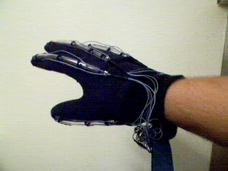
My DataGlove project is a series of short winded bursts of motivation that has led to a very primitive glove that works better then I had hoped. Now take into mind this is a garage dataglove and is in no way comparable to a real "Data Glove" or a type of pinchglove, but with more software work could serve its purpose.
Part of my reason for posting this project is that I searched and searched for a "how-to" on this subject when I first started getting interested into VR. With that in mind, I want to make it available to those who can find my site.

Materials needed for Glove Construction:
1. A glove. Latex is the best, fabric is easier to work with.
2. 5- Infared L.E.D. 's (Available at Radio Shack)
3. 5- Infared reciever's (Available at Radio Shack)
4. 3 ft of tube. (Black works the best)
5. 5- 1M ohm resistors
6. 5 - 150 ohm resistors
7. Ribbon Cable
8. A electronic kit box
9. Connectors for your A/D converter and glove circuit
10. An A/D converter (available at RainbowKits)
11. A keyboard extension cable
12. And please some common sense
The basic operation of the glove is a simple voltage divider. The emitter end of the sensor sends light to the detector. Depending on the position of your finger you will get somewhere between full light and no light. This varies the resistance of the detector thus changing the voltage at Vout according to the light received. This simple concept is used to create the dataglove sensors.
The first step is cutting the tubes to the length of your individual fingers and placing the emitter and detector in the ends of the tubes. I placed the emitters at my fingertips and the detectors at my knuckles.
Next is to attach the tubes with the sensors to the glove. I did this by sewing rings of thread at each knuckle joint on the glove. Just work with it alittle and you will find the right locations.
Now take the ribbon cable and seperate the individual strands about a foot, so you will have some room to work. Twenty wires will be needed. Four wires per finger. You can actually reduce the number of wires by using one wire to feed the supply voltage to all the fingers. The same can be true for the ground. I kept them all seperate for neatness and simplicity. Another note, be careful to connect the correct polarites to the emitters and detectors. Supply voltage to the anode and the ground path to the cathode of each emitter and detector. Refer to the package, that your emitter/detector came in, to verify the connections. Remember to wire the ribbon wires systematically so that when it comes time to connect to the circuit you know which wire goes where.
Attach the ribbon cable to the sleeve of the glove where the individual wires come back together. Now is the time to test your glove to make sure that your sensors are working before you go any further. Test each finger one at a time with a volt-meter and a power supply with a test circuit on a breadboard. The schematic is shown below. This is also the circuit that will be built five times for each finger and placed inside the electronic kit box, with your connectors.
If your circuit works and you get voltages out varying with finger flex then your doing it right. Next is to build your box with your five voltage dividers. I placed a DB-25 male connector at the end of my ribbon cable coming from the glove and placed a DB-25 female receptcle at the box like in the picture below.
For my power supply to the glove circuit, I spliced power from the keyboard port. Take a keyboard extension and use it for your power cord to the box. Cut the cord, splice into pin 5 for +5 volts. Check your port with a voltmeter to make sure. Also remember you'll need a ground so just as well take it off the keyboard port too.
For your +V outs from your circuit, use a connector that will fit your A/D Converter. I purchased a cheap A/D converter from RadioShack.com for 85 dollars. It is an 8 channel which will leave you with three that could eventually be used for x,y,and z cordinates for tracking or tilting applications. Connect your converter to the computer and run your software. Most Converters will come with a test program to read your inputs. Run the test program and make sure your getting readings. Verify that your glove works prior to connecting it to the converter. This will eliminate that side of the equation if you have any problems with your converter.
This dataglove design is analog. You could build a digital version with a built in RS-232 port and eliminate your converter completly. This would be rather simple with a microcontroller. If you have the equipment already to deal with programming microcontrollers, then a digital version would actually be a better and cheaper way to go.
If you have a Radio Shack converter, here is a REALLY basic program.
It will draw a hand on the screen that will mimic your movements and also print which finger is bent at the time. I'm not a programmer so if you can do it better feel free. This is only the third basic program I have ever written. Glove Program . It works well in DOS but may not work in some Windows enviroments. Also keep in mind that this is not a software application. It is merely a test program.
