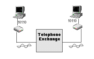
Why do we need a modem to communicate with other PCs over phone lines?
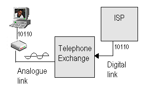
The computer operates, and therefore communicates digitally, using on and off electrical pulses, representing the digits 1 and 0 (binary). The normal telephone lines are analogue and can not carry these digital signals unless there is some form of convertion into analogue. The modem (MODulator/ DEMmodulator) converts these digital signals into an analogue signal which can be carried over the standard telephone lines.

How do these modems work?
The telephone systems have been specifically designed to carry human speech, and so therefore has a limited bandwidth. The exchange operates in the 300Hz - 3000Hz frequencies range, which is the range of human speech.
This limits the speed at which any digital signal can be transmitted over the telephone wires. The first Modems (e.g. 300 baud) used FSK (Fequency shift keying), where two different frequency tones were used to represent each bit. A high frequency and a lower frequency within the 300Hz - 3KHz range representing a 1 and 0. However, this greatly limited the maximum speed anyone would achieve over the existing telephone systems. Two frequency pairs had to be used, one for transmit and one to receive. Example:
| Bit | 1 | 0 |
| Transmit | 1270 Hz | 1070 Hz |
| Receive | 2225 Hz | 2025 Hz |
To overcome this problem, new modems were developed which used PSK (Phase shift keying) or DPSK (dibit PSK = 2 bits per phase change). A constant carrier frequency is used and the phase is shifted by a different angles to represent the data bits. It must be noted that the relative phase change determines the values, that is to say, the new phase compared to what it was before the change occured. The BELL 212A / V.22 standard using DPSK is used here as an example.
| Phase Shift (degrees) | 0 | +90 | -90 | +180 |
| Dibit Value | 01 | 00 | 11 | 10 |
At that same time, Amplitude modulation (AM) was also tried. The carrier's amplitude is raised and lowered to represent 1 and 0, while the frequency and phase remain constant.
These methods still left much (very much) to be desired. The real breakthrough in modems arrived when both Phase and Amplitude were used together.
The data bits are represented by both the amplitude and phase of the carrier wave.
This is called Quadrature amplitude modulation (QAM) or Multilevel Modulation .
An example of QAM for three bits per baud by using two amplitudes and four phase shifts could be illustrated as follows:
| Bit combination | Amplitude | Phase shift |
| 000 | Low | 0 deg |
| 001 | High | 0 deg |
| 010 | Low | 90 deg |
| 011 | High | 90 deg |
| 100 | Low | 180 deg |
| 101 | High | 180 deg |
| 110 | Low | 270 deg |
| 111 | High | 270 deg |
When dealing with amplitude (size) and phase (angle) we normally use vectors to simplify our understanding of these readings.
The figure below (figure 2), represents a very simple example of the above principle. 2 bits are represented by 1 cycle of the carrier, by having the signal modulated with a different phase (in this example 90 degrees difference between each 2 bits represented by the signal). The red points represents what is transmitted and what should be received by the modem on the receiving side. The signal, however, might become distorted before it arrives at the receiving modem and let us assume that what is received is represented by the vector with amplitude A and the angle O.
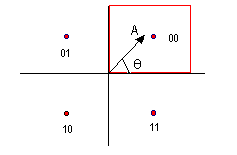
Since the received signal might not be the same as the transmitted signal, like what happened in the above example, we need a system which will cater for these errors. This problem is solved by assigning an area around the different points, these areas are called the decision areas. In the above diagram, the area covered by the red square is the decision area for the bits 00, meaning that any vector in this area will be treated as 00.
The difference between the transmitted vector and the received one creates a new vector called the error vector (see figure 3).
Each red point in figures 2 and 3 is called a symbol. A symbol is therefore a unique phase and amplitude combination, representing a set of bits.
The chart representing these symbol is called a constellation (since it looks like a whole lot of stars in space).
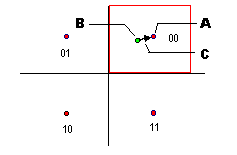
This not only applies to 33.6Kbps, but also to 14.4Kps. The decision area is too small to receive information with any degree of reliabilty, and so the only option is to increase the decision area, and this is accomplished by using Trellis coded modulation (TCM) .
With Trellis coding, the symbols are divided into a number of constellations, each symbol surrounded by a maximum sized decision area. The receiving modem has to know which constellation to use, and this is achieved by sending an extra bit per symbol (two dimension codes), or per every two symbols (four dimension codes), and then examining the sequence of the received symbols, since each constellation will have different transition states which are generated by this extra bit.
The error vector has been used by certain companies to their advantage with this extra space. The modem at the transmitting end deliberatly offset the transmitted vector slightly to the left or right (but obviously still remaining in the decision area), to represent 0 and 1. The receiving modem, knowing what the actual symbol point is within the decision area then determines the original offset, and knows wherether it represent a 0 or 1.
This information has been used to send diagnostic information between two modems. The information is sent multiple times, due to the probability of noise, and errors are therefore minimised.
The ITU V.61 standard uses this error vector to represent voice samples, therby allowing simultaneous voice and data transmission via the modem without affecting the data rate in any way.
Due to the limited transmitting power (and therefore limited signal amplitude), and noise (both Gaussian and quantization), as well as limited bandwidth, the absolute maximum speed which can be achieved using QAM, with a real-life telephone network noise level of 35dB and a channel bandwidth of 3000Hz, is 34822bps (modems have been standardised to 33.6Kbps).
Data Compression Standards
Error Correction Standards
| Name | Efficiency Rate | Packet Size |
|---|---|---|
| ASCII | NA | Variable |
| Kermit | 75% (128 bytes) | Variable up to 1024 bytes |
| X-modem | 78% | 128 bytes |
| X-modem 1K | ? | 1024 bytes |
| Y-modem | 80% | 1024 bytes |
| Z-modem | 95% | Variable |
| Sea-Link | 80% | 1024 bytes |
| Compuserve B | 80% | Variable |
Click here to get detailed information on protocols
Click here to get detailed information on the modem light indicators (signal LEDs)
Exactly how does the 56kbps modem work then?
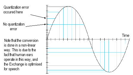
The basic theory behind their operation is quite simple. Most modern day telephone exchanges are digital. The exchange will receive an analogue signal from the phone line (which it assumes is human speech), and samples it 8000 times a second, converting the amplitude into an 8 bit digital code. This 8 bit code represent 256 (0 to 255) definable voltage steps. If a modem could receive these voltage steps, and convert them back again at 8000 times per second, it would be possible to receive 8000samples/second x 8bits/sample = 64000 bits/second.
However, the two biggest problems preventing this from being implemented are quantization noise, and the fact that the convertion is logarithmic and not linear.
I have had visitors since 13/11/1997!

For more, go to my Home Page