 First, in order to understand how a rectifier works,
you must have a general knowledge of the diode. The diode is made
up of semiconductor materials, like silicon or germanium. One side is made
of a P-type material, and the other an N-type material forming a junction
in this middle, thus forming a PN Junction Diode. The P-type side is called
the anode, while the N-type is the cathode. The diode can
be used to block current in one direction, and conduct it in the other.
This is called biasing. There are two biasing conditions, forward
biased and reverse biased. When the diode is forward biased, it conducts
current, when reverse biased, it blocks current. In order to forward bias
a diode, you must make the anode more positive than the cathode, to reverse
biase, you must make the anode more negative than the cathode. Don't worry,
it will all come together soon.
Purpose of the Rectifier.
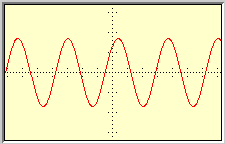
On the left you see a sine wave as seen on an oscilloscope.
Sine waves consist of 360 degree cycles. You can see how the wave curves
in the upward direction, and then down past the middle into the downward
direction. The curve in the upper portion of the wave is called the positive
alternation.
  The curve in the lower half of the wave is call the negative alternation.
Each alternation is 180 degrees of the complete cycle. The very top
and bottom of each alternation is called the peak. You have a negative
peak and a positive peak. Now if you were to look at a DC voltage on the
oscilliscope, you would see a straight line going across. This is where
the rectifier comes it. It's purpose is to turn that sine wave you see
above, into as close to a straight line as possible, or, conver an AC signal
into a pulsating DC. Go to the next page to
see how this works.