Power Driller
The Idea to build this machine is quite old. As stated in my hohepage, a computer has to do some special things. My computers have to controll machines or othe stuff. Because I more and more have to make printed circuit boards I decided to construct this funny thing. It is a real X-Y-Z machine which is not only able to drill, but can also mill. Software is written on a MSX 2 in Basic. Only a few routines which controlls the steppers itself are written in assembler.

To be able to drill a pattern which was originaly made by a professional software the resolution must be at least 0.05 mm each step. The whole mechanic is mounted on a 19mm chipboard. Most of the other parts are solid aluminium. To drive the 3 axis I use steppermotors originaly installed in the good old 5 1/4 " floppiydrives. To have a transmission with nearly no play, I use drivecables with a diameter of 0.5 mm. First trials with a kind of leadscrews were not realy successfull. two problem I had with leadsrew. 1st. Theye are quite expensive. 2nd. To compensate the play between srew and nut the software needs tu have extraroutines.
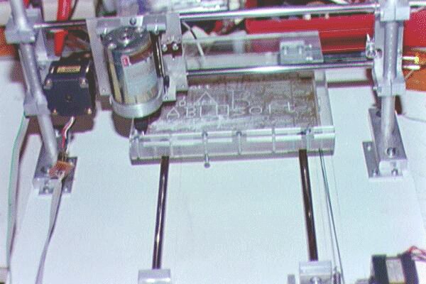
As You can see in this picture, the moving table is made from plexi. This is easy do work on. Much easier than aluminiun. And it looks very good. Doesn't it?

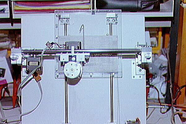
This table is able to move 17 cm in Y-direction. The X-movement is done by the X-drive. Installed on this X-drive is the driller with the whole Z-mechnism. To be able to drill or to mill parts with different thicknesses, for example a lighter, the whole X-drive can be moved up and down for about 5 centimeter. This is made by 15 mm diameter pilars with engraved rings every 5 mm. These rings helps me to move the drive parallely up and down.

The original driller itself was made by a 24 Volt DC-motor. This
motor I replaced with a Minimot Driller because it was not able to drill
15000 RPM. The speed of this motor is regulated. This is used to have the
possibility mot only to drill 0.8 mm holes in PCB but also larger diameters
for what ever I want to drill. To fix different drills this motor is equiped
with a precission Head. 
As You can see on the right photograph, all bearings are slidingbearings
from bronce. The slides on 2 every 10 mm in diameter polished steel shafts.
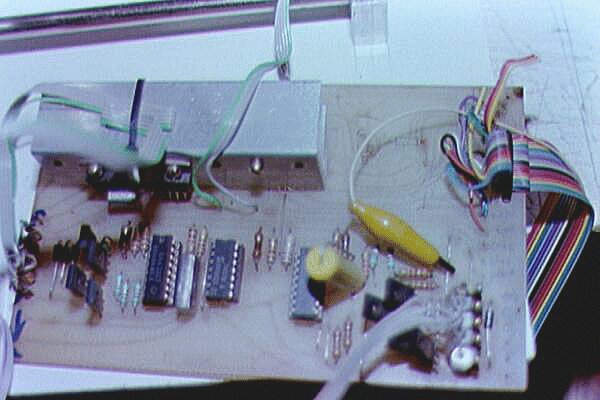
If You have a look to the wiring, You can see, there is no electronic eqipped
yet. To drive the first tests, I used a piece of electronic made from a
project in a quite old german electronic periodical called Elektor. Because
this part was used a lot of times for different experiments, it looks like
a heap of cables. Even
if it works fine to drive the first tests, I did not enjoy in it. So I
started to develop an own PCB for this project. It should be able
to drive 3 steppermotors. To be able to connect not only 12 volt steppers,
the steppervoltage have to be adjustable. Also the drillervoltage must
be adjustable. The 2 voltages are not adjustable by program but only by
hand. But they have also to be switchable. And this switching must be done
by programm. So 2 relays are installed on the board. The connect of this
board is made through the printerport of (not only) an MSX. This board
was designed with Protels Easytrax.
  By
the way, Easytrax is a freeware-software which can be downloaded directly
from Protels fttp site. There ar no restrictions in. It is a DOS software
which works excellently under OS/2, WIN3.11 and also WIN95. Klick
here, If You want to download. Something about how to make boards? Protel
Easytrax is able to write the results as HP-GL files do disk. Since
I'm owning a A-3 Plotter which I can feed with every pen I like, I make
boards directly on the plotter. I found that overhead projector pens from
 SCHWAN-STABILO
are suitable to do this job. The most important thing is to clean the board
as good as possible. then write directly with this pen to the coperside.
After a few minutes of driyng You can eatch the board with FE3 (Ferrum
trichloratum). The ink from this pens fixes as good on the board so it
is no problen th heaten the FE3 to about 40° centigrade. In about
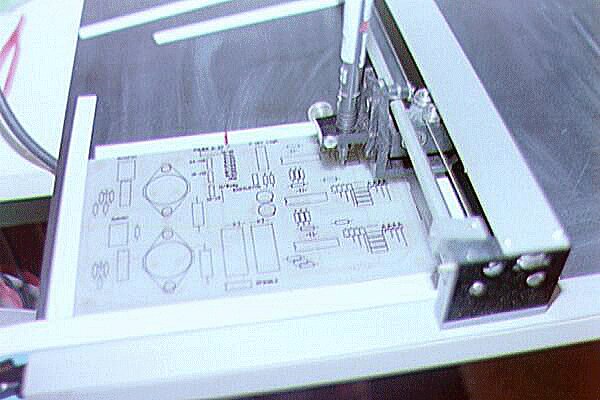
5 minutes, the board is finished. Because Easytrax allows to draw a component
drawing, I turn over the board and have the plotter to draw this on the
component side. Normaly I use Pens with the following descriptions: STABILO-OHPen
841. This is a black pen with a tip size "S". This gives lines
with about 0.4 mm and allows me to draw a single line between two IC-pads.
The pens are well known in Switzerland and Germany. If they are available
in other countries?
Any more question about this machine? E-mail me Back to the homepage