

Judiciously applied shunt capacitors can boost power factor, reduce
system losses, enhance voltage regulation, and release system
capacity for new load. Their application, however, can lead to
harmonic and transient problems which need to be addressed. This
article will help clarify some of the above benefits.
Sizing of Capacitor Banks
Fixed (unswitched) shunt capacitors are the least expensive way to achieve near unity power factor by providing a static source of leading reactive current. They can be installed either close to the highly reactive loads or at the service entrance.
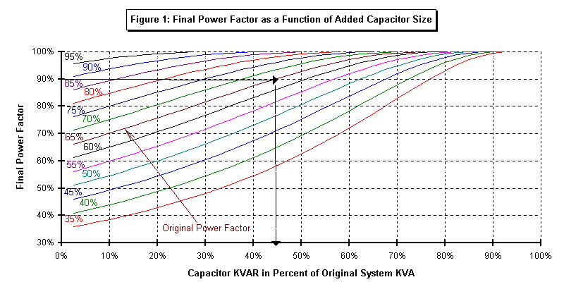
Sizing of a fixed capacitor bank required to achieve a utility mandated power factor is simple, as is shown in Figure 1. Systems with small differences between minimum and maximum loading can be designed for the average loading and fixed (non switched) capacitors can be applied. Systems with large load swings may need to have switched capacitors (with multiple steps) to avoid a leading power factor, overvoltage situations, and other concerns, as shown in this document. Switched banks are more expensive and lead to more transient and harmonic concerns for the system.

Figure 1 is provided for quick estimation of the additional kVAR needed to achieve a higher power factor. To use Figure 1, draw a horizontal line from the desired PF to intersect with the curve corresponding to the original PF. Extend a vertical line down to the horizontal axis and read the value for the required capacitor bank (given in percent of the original load kVA).
Example of the use of Figure 1: Original kVA of system 2500, Original PF = 65% Required capacitor size = 1100 kVAR (44% of 2500 kVA) for a desired PF of 90%.
When the thermal (ampere) limits are reached in cables, lines or equipment, corrective measures must be taken which normally involve :
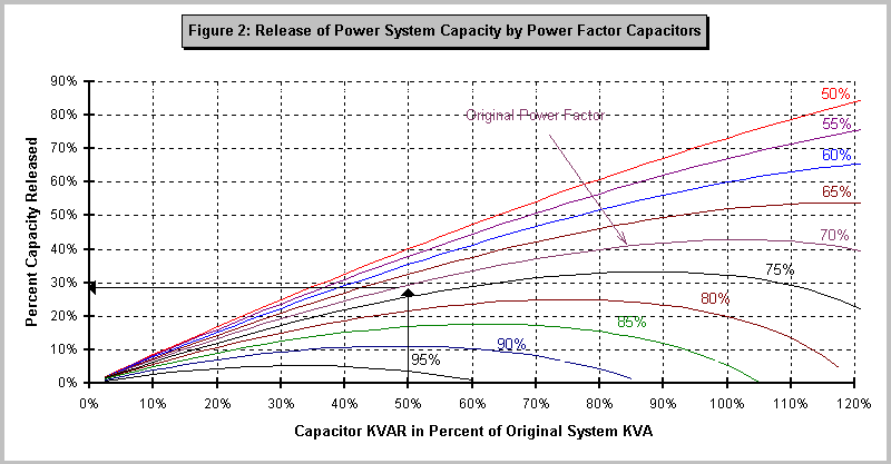
Of the three solutions, improving the power factor of the system through the addition of capacitors is usually the most economical. Improving the power factor of a system will lead to a reduction in current in the existing system permitting additional load to be served. Figure 2 shows the approximate capacity which could be released in a system due to the addition of power factor correction capacitors. It should be noted however that the size of the capacitor bank should be carefully chosen, since overcompensation will be counterproductive (the curves bend downward beyond certain capacitor values).

Example of the use of Figure 2: If a system load is 1000 kVA at 70% PF, adding a 500 kVAR capacitor bank (50% of the original system kVA) will release approximately 27% of the system's electrical capacity for new load (same PF as original load). The new load will have a PF of almost 0.9.
Reduction of System Losses
Reduction of system losses cannot usually justify the use of power factor correction capacitors, it is however an additional benefit from their application.
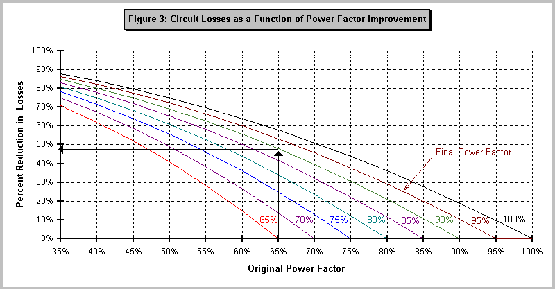
System losses can be reduced by increasing the power factor. Figure 3 illustrates the reduction in system losses when power factor capacitors are installed. Losses usually vary between 2 and 8 percent of the load kilowatts hours, and hence a 50% reduction in them would translate to 1 and 4% savings in the electrical bill. For large industrial plants this can lead to a welcomed savings. Losses and, hence savings, in rural distribution or commercial buildings, served at utilization voltages, will be more substantial.

Example of the use of Figure 3: Original PF= 65%, Final PF = 90% Reduction in losess = 48%.
Reduction of Voltage drop
Adding power factor capacitors will boost the system voltage by virtue of the reduced total current drawn by the system. Installed near the reactive loads, shunt capacitors will eliminate the need to provide the reactive current form the utility and reduce the total amount of current flowing through the conductors and transformers. The shunt capacitors draw leading reactive currents components which subtract from the lagging reactive current components drawn by loads such as induction motors. A reduced lagging reactive current will yield a voltage rise in inductive circuits. Calculating the magnitude of this rise in voltage is a complex iterative process, and is not presented here.
The application of capacitors for power factor correction and voltage support must be carefully considered to prevent operating difficulties and potentially damaging overvoltages. System load variations and the type of loads served must be evaluated in the analysis. Each system is unique and solutions should be modeled on a computer to determine the optimum type of capacitor system, amounts of correction needed and where it should be installed. We utilize several different analytical tools and computer programs for the evaluation of electrical systems and determination of the best and safest approach to power factor improvement.
 Back to Power Engineering Notes Page