Hi, I am Tony I0JX
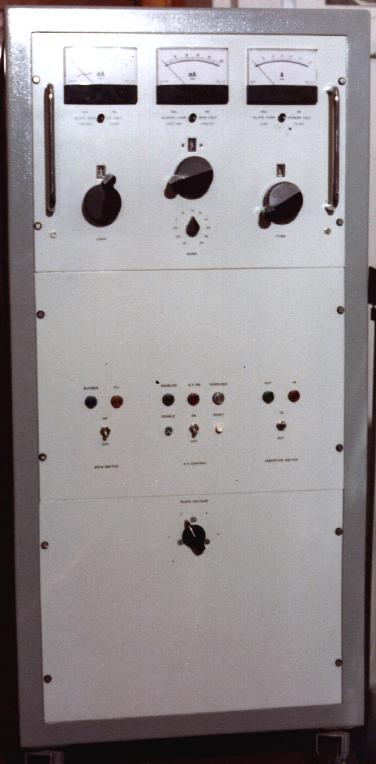
A BIG home-made linear
In the 70ies I was much more committed to DXing and contesting than today, and having a big linear was a must at that time. After building some amplifiers with EIMAC 4CX3000A and 4CX5000A, in 1981 I decided to build one using a single grid-driven 4CX10000D / 8171, which was intended for a contest station. After so many years, I hope that God has forgiven me for not having strictly observed our power limits, and I then feel myself free to tell the story to those who may be interested in it.
All began at an hamfest many years ago, when I found several 4CX10000D / 8171 NOS tubes, still in their original vacuum-sealed packaging. The label on the box indicated that those tubes had come from an US Air Force Base in Thule, Greenland. Price was fairly good and I bought several of them.
The second step was to find the tube socket, a potentially very expensive item. A surplus store in Roma happened to have, who knows how, several new SK-300 EIMAC sockets on sale at reasonable price, so I bought them. At that point, I had already got a clear vision of how the new linear amplifier should look like. And it eventually became a reality.

The linear was powered by two single-phase 7-kW 230 VAC. As a matter of fact with SSB or CW the average power consumption is no more than 50% of the key-down value; furthermore alternating transmission and reception periods further decreases the medium-term average.
To evenly share the load between the two AC lines, I actually built two separate 3,250 VDC power supplies, one for each AC line, and I then put the two DC voltages in series, for a total of 6,500 VDC. The power supplies utilised a plain input-capacitor filter, and the voltage under no-load conditions raised up to nearly 7,500 VDC. With the plate idle current (500 mA) voltage was some 7,200 V, so the power supply regulation across the whole tube active region was fairly good (about 10%), despite the visible AC line voltage drop.
As shown in picture below, the whole plate supply is housed in the bottom compartment of the rack.

The middle compartment hosts the filament supply (7.5 V @ 75 A), the stabilised grid supply (-350 VDC, adjustable) and the stabilised screen supply (1,250 VDC @ 300 mA) which utilised a 4-400A tetrode as series regulator. This tube can be seen in picture below, close to a big transformer and just below the high-pressure blower.
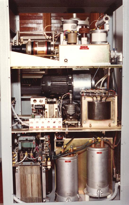
The top compartment hosts the RF deck which you can here see from the top.
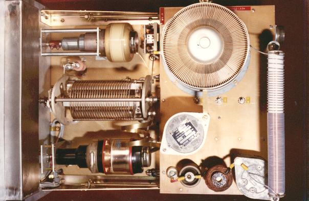
The Pi-network utilises two vacuum capacitors and a rolling inductor, with no need for an RF power switch. The big mica capacitor near the centre of the picture is the plate coupling capacitor. The bottom plate of that capacitor also constitutes one armature of the neutralization capacitor, as one can better see in picture below.
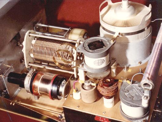
By the way, neutralization is absolutely necessary for an high-gain amplifier delivering maximum power with just some 80 W drive power. The optimal value for the neutralization bridge ground-side capacitance is different for each band, so the band switch must have a wafer dedicated to switching capacitive trimmers, to perfectly null the bridge on each band. The band switch actually has 11 positions, as one can see in picture below (the 1.8 MHz and 29 MHz positions were cut out of the picture).
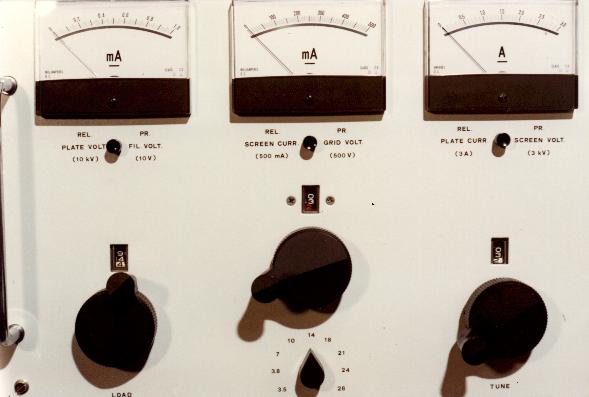
Another wafer of the band switch is dedicated to switching adjustable coils, one per band, which are intended to resonate the fairly high grid capacitance (115 pF), so as to obtain a good input SWR. By the way, the driving signal from the exciter is directly terminated on a 100-W 50-ohm resistor, in parallel to which there is a 7:1 step-up transformer raising the input RF voltage to a level sufficient to drive the 8171 grid. I can assure you that having this machine to properly work with a good input SWR across the whole 1.8-29 MHz frequency range was not at all a trivial task.
Picture below shows the back of the amplifier, and the cables interconnecting the three compartments.

It was possible to obtain an RF power of 11 KW (key-down carrier) on all bands. Power was measured with a Bird 4712 wattmeter and a 25 KW slug (see my page on Bird test equipment).
Frankly speaking, I am afraid that today I would hardly make all that work again. But I still like to remember the good old days.
Return to the I0JX home page
This page hosted by ![]() Get your own Free Home Page
Get your own Free Home Page