
None
Analog-Digital Converter, this electronic components are used to digitize analogous measuring-signals and make them readable to microprocessors. Depending on the required accuracy the digitizing is performed with 8, 16 or 24 bit resolution.
an important message, sent imediately to the central monitoring system
Dragging is used to move an object on the screen from one location to another. Dragging is also used to resize an object by moving the objects border. Click and hold down the mouse button to move or resize an object.
A focus is a visible border or color-effect emphasizing preselected controls
A filter is used to prevent invalid character-input. The set of valid characters are usually annotated with rectangular brackets, for instance
[0-9], [ASCII 32-127]
Final-Values are the result of the signal-postprocessing. Post-processing is used for data-correction by applying calibration-values, or if the use of different technical units is required for data-evaluation (i.e. ppm versus µg, or m/sec versus km/h).
A Graphical User Interface (GUI) allows the user to interact with the system in a shophisticated way.
Halfhour-Meanvalues (HMV) are the result of the standard data-processing. The environmental monitoring system is capable to store up to 21 days of HMV for up to 48 components.
A component may be a physical or a logical component. For instance the wind-gust is described by 3 logical components: wind-gust, related wind-direction and related time-marking of the occurence.
A progress-bar is an indicator showing the progress of timeconsuming operations
Raw-Values are the result of the signal-conversion - the electrical input-signal is converted in technical units by use of a polynomial. For instance the signal-voltage of the temperature-sensor is converted in °Celsius.
RS-232 is a communication-link used for data-transfer over short distances (suitable for up to 15 meters of cable-length).
The sub-identifier is used to distinguish devices of same type. The unique Device ID consists of two digits describing the type of measuring device (ie. temperature sensor = 13) and a sub ID from 1 - 9.
The task-bar is used by the operating system (ie. Win98, WinNT) to indicate running user-applications. A small part of the task-bar is provided for system-activities, for instance time-display.
A hooverhelp or tooltip is used to explain abbreviations or technical expressions
A User Password is required to access data or execute operations
Variable-Meanvalues (VMV) are the result of user-defined data-processing. VMVs may be established for up to 8 components. The storage of VMVs depends on the number of components and the choosen time-interval.
The environmental monitoring system is capable to store exactly 3 days of VMV for 8 components with measuring-intervals of 1 minute. If the number of components is decreased, or the time-interval is increased, the storage-capacity will increase accordingly.
For detailed information see the W3C homepage at
www.w3.orgNot yet implemented
Uwedat® Servicetool
Station Parameter
Introduction
The station parameters determines the identity and behaviour of the environmental monitoring station. These parameters comprises unique station identifiers, communication-settings like telphone numbers and modem-types, alarm recognition and alarm-schedules.
Overview
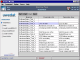
The Station Parameter view is a tabbed pane divided into four editable tables. Each table contains a set of parameters. Click on the overview-list to see a short description to each parameter-table.
Parametertable
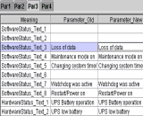 The parameters are grouped into three columns. The first column shows the meaning of the parameter and the second column shows the value of the parameter. The third column contains editable datafields which allows you to edit the parameter-value.
|
Parameter Editing
The third column (titled Parameter New) contains editable entryfields which allows you to edit the parameter-value. Doubleclick into the entryfield and make your changes.
 | Entryfields are usually combined with filters to prevent invalid data-input. If a filter is applied with an entryfield, the set of valid characters is described in rectangular brackets. It is important to know, that such entryfields doesn't accept data-input which violates the formatting-rules. |
|
Parametertable 1
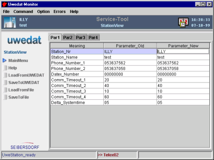
Parameter-table 1 contains parameters to specify the identity and communication settings of the environmental monitoring station:
Station ID Setting of station name and number
Communication Setting of telephone and Datex-P numbers
TimeoutsSetting of communication and retry-timeouts
Time Sync Specifies maximum time difference with the central measuring system
|
Parametertable 2
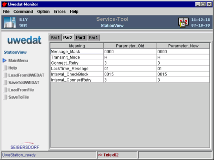
Parameter-table 2 contains parameters to specify the communication device and the handling of error events:
Transmission mode Select modem, leased line or data-island
Error Message Mask Setup internal error-message generation
Error MessagesSetup retries and blocking-times
|
Parametertable 3
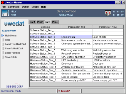
Parameter-table 3 contains descriptive parameters which explains the meaning of status-bits in plain text:
Software Status The meaning of Software Status-Bits
Hardware Status The meaning of Hardware Status-Bits
|
Parametertable 4
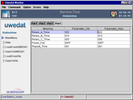
Parameter-table 4 contains parameters to specify emergency schedules:
Alarm RelaysConfigure emergency shutdown relays
Alarm Schedule Setup emergency shutdown schedule
|
Menu
The Station Parameter Menu is used to transfer the configuration parameters from and to the environmental monitoring station and to copy the configuration to a backup-archive (harddisk or floppy).
A usual approach to setup a new environmental monitoring station is to load a prepared or a standard configuration from your backup-archive, set the proper station ID and station-name with the Servicetool and save the configuration to the station.
File Dialog
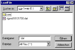
The look and behaviour of the file-dialog depends on the operation system of your Service-Tool PC. The example shows a file-dialog used with the operation system MS Windows.
|
 Top of document
Parametertable 1
Image
Parameter
The parameters are grouped into three columns. The first column shows the meaning of the parameter and the second column shows the value of the parameter. The third column is an editable datafield which allows you to edit the parameter-value.
 Station ID
Identifies the station within a measuring network. Numerals and upper-case letters can be used. Station ID
Identifies the station within a measuring network. Numerals and upper-case letters can be used.
 |
LENGTH : 4 char
FORMAT : [0-9] [A-z] underline_
EXAMPLE: 123A
|
|
 Station Name
Name of the station in plain text. Station Name
Name of the station in plain text.
 |
LENGTH : 20 char
FORMAT : [ASCII char 32 - 126]
EXAMPLE: Teststation_012
|
|
 Telephone Number
Priority number (1) and alternative number (2) for automatic internal alarm messages by telephone. Telephone Number
Priority number (1) and alternative number (2) for automatic internal alarm messages by telephone.
 |
LENGTH : 20 char
FORMAT : [Digit 0 - 9] >
EXAMPLE: >471101234
|
|
 Datex-P Number
For automatic internal alarm messages. Datex-P Number
For automatic internal alarm messages.
 |
LENGTH : 12 char
FORMAT : [Digit 0 - 9]
|
|
 Sync_Block Timeout
Time between two DDCMP synchronisation blocks in the start-up phase (Comm_Timeout_1). Sync_Block Timeout
Time between two DDCMP synchronisation blocks in the start-up phase (Comm_Timeout_1).
 |
LENGTH : 2 char
FORMAT : [Digit 0 - 9] in seconds
DEFAULT: 20 seconds
|
|
 Telegram Timeout
Maximum time within which a telegram must be acknowledged with ACK (understood) or NAK (repeat), (Comm_Timeout_2). Telegram Timeout
Maximum time within which a telegram must be acknowledged with ACK (understood) or NAK (repeat), (Comm_Timeout_2).
 |
LENGTH : 2 char
FORMAT : [Digit 0 - 9] in seconds
DEFAULT: 40 seconds
|
|
 Data Message Timeout
Timeout for telegram acknowledgement in order to optimise pipelining in the event of multiple telegrams (only last telegram is acknowledged), (Comm_Timeout_3). Data Message Timeout
Timeout for telegram acknowledgement in order to optimise pipelining in the event of multiple telegrams (only last telegram is acknowledged), (Comm_Timeout_3).
 |
LENGTH : 2 char
FORMAT : [Digit 0 - 9] in seconds
DEFAULT: 10 seconds
|
|
 Application Timeout
Interval between periodic checks of the connection to the communication partner if there is no data traffic (Comm_Timeout_4). Application Timeout
Interval between periodic checks of the connection to the communication partner if there is no data traffic (Comm_Timeout_4).
 |
LENGTH : 2 char
FORMAT : [Digit 0 - 9] in seconds
DEFAULT: 60 seconds
|
|
 Delta System Time
Default maximum time difference between environmental monitoring station and central monitoring system. Automatic synchronisation if exceeded (data processing is restarted if there is a difference of 5 minutes or more!). Delta System Time
Default maximum time difference between environmental monitoring station and central monitoring system. Automatic synchronisation if exceeded (data processing is restarted if there is a difference of 5 minutes or more!).
 |
LENGTH : 2 char
FORMAT : [Digit 0 - 9] in minutes
DEFAULT: 05 minutes
|
|
 Top of document
Parametertable 2
Image
Parameter
The parameters are grouped into three columns. The first column shows the meaning of the parameter and the second column shows the value of the parameter. The third column is an editable datafield which allows you to edit the parameter-value.
 Message Mask
Mask bits set to "1" lead to an internal message if the corresponding status bit is present, mask bits set to "0" prevent an internal message. The bit-order is from bit 8 to bit 1 Message Mask
Mask bits set to "1" lead to an internal message if the corresponding status bit is present, mask bits set to "0" prevent an internal message. The bit-order is from bit 8 to bit 1
 | Mask 1 = software status (CPU-board) |
 | Mask 2 = hardware status (Status-Interface board) |
 |
EXAMPLE: 00000110 10001000
|
|
 Transmission Mode
Determine the type of data transmission used with the central monitoring system, the following parameters are applicable: Transmission Mode
Determine the type of data transmission used with the central monitoring system, the following parameters are applicable:
 | D = Datex P 300 Baud |
 | 2 = Datex P 2400 Baud |
 | I = Data Island (no communication link) |
 | T = Telephone |
 | S = Leased line (steady line) |
 | H = Hayes Mode |
|
 Connection Attempts
Maximum number of successive connection attempts (connect_Retry) with the central monitoring system. Connection Attempts
Maximum number of successive connection attempts (connect_Retry) with the central monitoring system.
 |
LENGTH : 1 char
FORMAT : [Digit 0 - 9]
DEFAULT: 3
|
|
 Connection Interval
Time period (timeout) in minutes between connection attempts (Interval_ConnectRetry). If two telephone numbers have been entered, these are dialled alternately. Connection Interval
Time period (timeout) in minutes between connection attempts (Interval_ConnectRetry). If two telephone numbers have been entered, these are dialled alternately.
 |
LENGTH : 1 char
FORMAT : [Digit 0 - 9] in minutes
DEFAULT: 3 minutes
|
|
 Dial-Up Interval
Time period (blocking time) in minutes between connection attempt packets (Interval_CheckBlock). Dial-Up Interval
Time period (blocking time) in minutes between connection attempt packets (Interval_CheckBlock).
 |
LENGTH : 4 char
FORMAT : [Digit 0 - 9] in minutes
DEFAULT: 0015 minutes
|
|
 Message Interval
Time period (blocking time) in hours between successive internal-messages. Message Interval
Time period (blocking time) in hours between successive internal-messages.
 |
LENGTH : 2 char
FORMAT : [Digit 0 - 9] in hours
DEFAULT: 03 hours
|
|
 Top of document
Parametertable 3
Image
Parameter
The parameters are grouped into three columns. The first column shows the meaning of the parameter and the second column shows the value of the parameter. The third column is an editable datafield which allows you to edit the parameter-value.
 Software Status
Meaning of the software status bits of the CPU-board in plain text. Free bits currently not in use. Software Status
Meaning of the software status bits of the CPU-board in plain text. Free bits currently not in use.
Bit 1: not used
Bit 2: not used
Bit 3: Data lost
Bit 4: Maintenance Mode
Bit 5: System-Time changed
Bit 6: not used
Bit 7: Watchdog was active
Bit 8: Stationsrechner-Ausfall
|
 Hardware Status
Meaning of the hardware status bits in plain text. Partly predetermined or reserved. Hardware Status
Meaning of the hardware status bits in plain text. Partly predetermined or reserved.
 |
EXAMPLE: Power fail
|
|
 Top of document
Parametertable 4
Image
Parameter
The parameters are grouped into three columns. The first column shows the meaning of the parameter and the second column shows the value of the parameter. The third column is an editable datafield which allows you to edit the parameter-value.
 Relay Time
To prevent measuring-devices from irregular states during power-fail or ambient temperature exceedings, a scheduled shutdown is provided by means of relays: Relay Time
To prevent measuring-devices from irregular states during power-fail or ambient temperature exceedings, a scheduled shutdown is provided by means of relays:
 | Relay A = scheduled shutdown of measuring-devices O3, NOX, SO2, CO |
 | Relay B = scheduled shutdown of measuring-device Dust |
 | Relay C = scheduled activation of container fan |
 |
LENGTH : 3 char
FORMAT : [Digit 0 - 9] in minutes
EXAMPLE: 003 minutes
|
|
 Power Fail
Determines the trigger condition for the scheduled shutdown of measuring-devices. The trigger may be: Power Fail
Determines the trigger condition for the scheduled shutdown of measuring-devices. The trigger may be:
 |
LENGTH : 4 char
FORMAT : [Hexadecimal 0 - F] logical OR of the statusbits coded in two doublebytes
EXAMPLE: 03FF
Software statusbit 1 and 2 (03)
all Hardware statusbits (FF)
|
|
 Repeat Time
The Repeat Time prevents discharging of the emergency power supply in case of successive power-fails. Repeat Time
The Repeat Time prevents discharging of the emergency power supply in case of successive power-fails.
 |
LENGTH: 3 char
FORMAT: [Digit 0 - 9] in hours
EXAMPLE: 001 hour
|
|
 Top of document


 The Station Parameter view is a tabbed pane divided into four editable tables. Each table contains a set of parameters. Click on the overview-list to see a short description to each parameter-table.
 The parameters are grouped into three columns. The first column shows the meaning of the parameter and the second column shows the value of the parameter. The third column contains editable datafields which allows you to edit the parameter-value.


