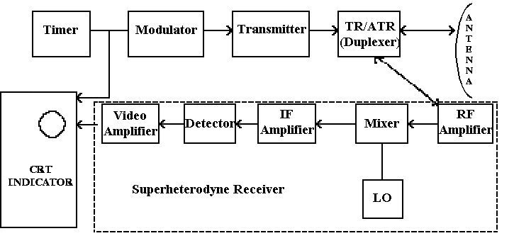
Figure 1-1.— Basic radar system.
TOPIC 1
RADAR
INTRODUCTION
The invention of radar just prior to World War II (WWII) changed forever the nature of warfare. Radar eliminated many of the human limitations. Furthermore, it virtually eliminated the possibility of a sneak attack by enemy aircraft. The word "radar," first used in 1940, is an acronym formed from the words, radio, detection, and ranging.
Radar operates on the principle that objects in the path of radio waves reflect or reradiate some portion of the wave, enabling those objects to be detected and tracked at long range distances far beyond what the unaided eye can see. Radar cannot resolve detail as well as the eye, nor is it capable of recognizing the color of an object; however, it can see through darkness, haze, fog, rain, and snow, which the eye cannot. In addition, radar can measure the distance or range to the object. Radar can also determine the speed and size of the object, and direction to the object. Most radars operate at frequencies between 50 and 20,000 megahertz (MHz); an increasing number are operating in the 20 to 100-gigahertz (GHz) range.
HISTORY OF RADAR
A British physicist, James Maxwell, developed equations governing the behavior of electromagnetic waves in 1864. In Maxwell’s equations are the laws of radio-wave reflection. The German physicist, Heinrich Hertz, first demonstrated these principles in 1886. In the early 1900s, a German engineer obtained a patent for an obstacle detector and ship navigational device. He demonstrated his device for the German Navy, but since technology was not sufficiently adequate to obtain ranges of more than about a mile, his device was dismissed on the grounds it was only a little better than a visual observer. Marconi recognized the potential of short waves for radio detection and based on the earlier work done by Hertz, suggested in the 1920s that electric waves can be completely reflected by objects. The Naval Research Lab (NRL) experimented with radio detection in the 1920s. They used continuous wave (CW) interference radar with a 5-meter wavelength and a separate receiver and transmitter to detect a wooden ship.
The first radar systems used CW to detect an object. These radars depended upon the interference produced between the direct signal received from the transmitter and the Doppler frequency shift signal reflected by a moving target. This type of radar was originally called a CW interference radar but today is called a bistatic CW radar. The first experimental detections of aircraft used this radar principle.
In 1935 two British scientists were responsible for the most important advance made in the technology of radar during WWII. Henry Boot and John T. Randall invented an electron tube called the resonant-cavity magnetron. This tube is capable of generating high-frequency radio pulses with large amounts of power, thus beginning the development of microwave radar.
Researchers recognized that the limitations to obtaining adequate position information could be overcome with pulse transmission. The first successful demonstration of a pulse radar in the United States (U.S.) occurred in 1936. This radar operated at 28.3 MHz, making it too large for shipboard application. In less than three months, a 200-MHz radar was demonstrated. This radar was the first to use a duplexing system with a common antenna for both transmission and reception. In the spring of 1937, this radar was installed and tested on the destroyer USS LEARY.
The British had demonstrated the pulse radar technique almost a year earlier. They felt the nearness of WWII much more than the United States and expended a huge effort on radar development. The British established the first practical radar system in 1937. They established a chain of radar stations along the south and east coasts to detect aggressors in the air or on the sea. By the 1940s and the outbreak of WWII, the first useful radar systems were in place. Germany, France, Great Britain, and the United States all used radar to navigate ships, guide airplanes, and detect enemy craft. Other countries such as Japan, Italy, and Russia apparently did not enter the field of radar development until after they became aligned with either Germany or the Allied powers.
It is interesting to note that the Army, in 1939, had developed a long-range radar, the SCR-270, for early warning. This radar was in use in Hawaii in 1941. It detected the Japanese planes used during the bombing raid of Pearl Harbor before they reached the island. Unfortunately, the significance of the blips on the radar scope was not realized until after the bombs had fallen.
Radar was originally developed to satisfy the needs of the military. At the close of WWII, the pace of radar development slowed. During the 1940s, the most significant advance was the development of the magnetron, a device for generating high-power microwave pulses. During the 1950s, the introduction of the high-power klystron amplifier was significant. The advantage of the klystron over the magnetron is that it is capable of greater power output and is more stable. Additionally, the klystron amplifier allows for better moving target indication (MTI) radars.
The major user of radar, and contributor of the cost of almost all its development, has been the military. For example, the development of the airborne intercept (AI) radar was designed so that most functions controlled by the pilot such as aiming and firing of weapons could be taken over by the radar and a computer. This advanced technology was also made possible by the concurrent development of the electronic computer. During the post WWII era, radar became more accurate because of the more accurate tracking requirements needed by guided missiles. With the advent of Sputnik and intercontinental missiles, radar ranges became greater. Civilian usage of radar has mainly been for marine and air navigation.
RADAR THEORY
The objective of a radar is to transmit radio frequency (RF) energy toward a target and to receive and process the reflected energy. Radar equipment can be divided into three basic component groups: the transmitter, the receiver, and the antenna. The complexity of the transmitter and receiver depends upon the modulation format and the signal processing methods used. Radars are divided into two broad categories, CW and pulsed. These categories are further divided into other categories such as frequency modulated (FM)-CW, pulsed Doppler, etc. Radar antenna characteristics are directly related to the radar frequency and operational expectations.
The basic parts of a radar system are illustrated in the simple block diagram shown in figure 1-1. Usually, the same antenna is used for both transmitting and receiving (i.e., the radar is monostatic).

Figure 1-1.— Basic radar system.
TIMER
The timer, the heart of the pulsed radar, generates the trigger pulses at the specific pulse repetition frequency (PRF). Sometimes the timer is referred to as the synchronizer. Each timing pulse turns on the modulator. The timer ensures that all circuits connected within the radar system operate in a definite time relationship with each other, and that the interval between pulses is of the proper length. The specific function of the timer is to produce trigger pulses that start the transmitter, indicator/display sweep circuits, and ranging circuits. The timer has two outputs, one to the modulator and one to the display/indicator unit. Examples of older radar timing circuits that were not very stable and newer radar timing circuits with greater stability are shown in table 1-1.
Table 1-1.— Timing CircuitsOlder Radars |
Newer Radars |
Power line synchronization |
Delay line |
Rotary spark gap |
Crystal controlled |
Self-excited oscillator |
MODULATOR
The modulator, triggered by the timing pulses, produces an output pulse of the required shape and duration with sufficient power to the transmitter. The modulator controls the radar pulse duration (PD) by means of a rectangular direct current (DC) pulse of the required duration and amplitude. The modulator also maintains the intervals between pulses. The peak power of the transmitted RF pulse depends on the amplitude of the modulator pulse.
TRANSMITTER
The transmitter is basically a simple oscillator that produces an RF output for the duration of the pulse provided by the modulator and sends it to the duplexer. A variety of oscillators used in radar transmitters exists, such as a magnetron, klystron, traveling-wave tube, crossed-field amplifier, or solid-state device.
DUPLEXER
The antenna is shared for the transmitting of RF energy and the receiving of returned energy. A fast-acting electronic switch, called the transmit-receive (TR), blocks the high-power transmitted signal from the receiver
during transmission to protect the sensitive elements of the receiver. After the transmission, the switch opens the receiver to the antenna blocking the transmitter so that all available returned energy passes to the receiver. The antitransmit-receive (ATR) switch, which has no effect during the transmission portion of the cycle, now channels the received signal power into the receiver. The TR and ATR together are called the duplexer. The duplexer, which permits the single antenna to be time shared for both the transmission and reception, is responsible for channeling the transmitted power to the antenna and the returned energy to the receiver.
ANTENNA
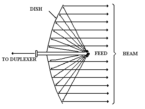
The antenna is connected to the duplexer by a coaxial cable or waveguide. The transmitter power is radiated into space by a highly directional, high-gain antenna that concentrates the energy into a narrow beam. Most antennas used in radar applications are variations of the parabolic reflector antenna. The antenna radiates the radio waves into a parabolically shaped dish. The dish reflects the waves in the form of a narrow beam that is parallel to the feed. See figure 1-2. The narrow, directive beam that is characteristic of most radar antennas not only concentrates the energy on target but also permits a measurement of the direction to the target. On reception, the antenna collects the energy contained in the returned signal and delivers it to the duplexer. The shape and size of the antenna depends upon its use and the RF it radiates and receives. The design of the antenna determines its directivity and gain.
RECEIVER
The function of the receiver is to detect desired signals in the presence of noise, interference, or clutter. The receiver processes the returned energy and sends the signal to a display indicator. The radar receiver is usually of a superheterodyne type. Target detection is accomplished in the receiver. The received signal passes through an RF amplifier where it is amplified. (Many microwave receivers do not have an RF amplifier but use the mixer as the first stage.) The RF signal then enters the demodulator where the mixer and the local oscillator convert the RF signal to an intermediate frequency (IF). Combining the RF signal with a frequency generated by the local oscillator (LO) creates the IF. The IF signal enters the IF amplifier where it is amplified and then passed on to the detector. The detector converts it to DC and filters the IF energy resulting in a signal pulse in video form. The signal pulse then passes to the video amplifier where it is increased in strength and cleaned up. The signal pulse is then displayed on some type of display, usually a planned position indicator (PPI) scope.
When Doppler processing is employed, as it is in CW, MTI, and pulse Doppler radars, the detector compares the Doppler frequency shift to a reference signal at the transmitted frequency. Additionally, there are filters that reject the stationary clutter (no shift in Doppler frequency) and pass the Doppler-frequency-shifted signals from the moving targets.
INDICATOR
The indicator presents the processed signal in a variety of display formats on a cathode ray tube (CRT). The particular display depends upon what information is desired and how the radar is used. No matter which display is used, the timer pulse begins the display cycle and the target signal is presented at some time during this cycle. The presentations in table 1-2 are commonly used to display radar returns.
TRANSMITTER DESIGNS
Active radars may be divided into two major groups according to the transmitted waveform. The two major groups are CW and pulsed. The two differences between CW and pulsed radars are that CW radars transmit continuously and that in a CW radar a portion of the transmitted energy is sent to the detector. Pulsed radars are used extensively in military applications.
Table 1-2.— Common Radar DisplaysType |
Description |
A |
Displays time versus amplitude. Oldest of all scope presentations. Used to set range gates. |
B |
Displays range and azimuth. Trace sweeps from side to side and targets appear as intensity-modulated dots. Used in conjunction with fire-control radar. |
C |
Displays elevation versus azimuth. As radar scans, the target echo is displayed as a blip on the CRT at the point of strongest return. Used in fighters and interceptors. |
E |
Displays range and elevation information. Targets appear as intensity-modulated dots. Used for height finder radars. |
G |
Displays target elevation on the Y-axis, relative azimuth on the X-axis, and range as the blip shape on the screen. |
P |
Displays target range and azimuth (PPI scope). Most well-known of all presentations. Targets appear as intensity-modulated dots. |
CONTINUOUS WAVE RADAR
The Doppler effect is the basis for CW radar. When a radar transmits a wave of a certain frequency (f0), the wave that is reflected back to the receiver will be shifted in frequency by a certain amount (+/- fd). See table 1-3. This shift in frequency is known as the Doppler effect. The difference in frequency between the transmitted and reflected energy indicates both the presence and speed of a moving target. The CW radar uses this Doppler effect to obtain the desired information on a target of interest. Disadvantages to the Doppler system are that the range of the object cannot be determined, it cannot differentiate between objects when they lie in the same direction and are traveling at the same speed, and it cannot handle multiple targets. Moreover, it cannot locate stationary or slow-moving objects, which a pulsed radar can detect.
Table 1-3.— Doppler Shift
When the Doppler frequency is |
Then the target is moving |
Positive (+) |
Toward, or closing in on, the radar. |
Negative (- ) |
Away from, or opening from, the radar. |
Early applications of the CW radar were the proximity fuse and the FM-CW altimeter. An example of the Doppler effect is the changing pitch of the whistle of an approaching train. As the train approaches, an increase in pitch (increase in frequency) is heard; as the train moves away, a decrease in pitch (decrease in frequency) is heard. One of the uses of the CW radar of closest concern to you is its use as a radar speed "gun" used by traffic enforcement agencies.
The transmitter and the receiver of a CW radar are coupled through the antenna since the receiver requires a small amount of the transmitted signal for a reference. Some isolation (physical separation) is required between the transmitter and the receiver except when the CW radar operates with relatively low power or has an insensitive receiver. The amount of isolation in a CW radar is determined by the noise that accompanies the transmitter leakage. The transmitter noise of concern in Doppler radars is those that are in the same frequency range as the expected Doppler frequencies.
To track an object with CW Doppler, radar range must be determined. Since Doppler frequency is not directly related to range, another method is needed to determine the range. By using two separate transmitters that operate at two different frequencies (F1 and F2), you can determine range by measuring the relative phase difference between the two Doppler frequencies. In such a system, a mixer is used to combine the two transmitted frequencies and to separate the two received frequencies. The use of the mixer permits the use of one transmitting and receiving antenna.
Additionally, instead of using two transmitter frequencies, you can find the range by sweeping the transmitter frequency uniformly in time to cover the frequency range from F1 to F2. The beat, or difference, frequency between the transmitted and received signals is then a function of range. In this type of CW radar, the range as well as the speed is measured.
FREQUENCY MODULATED-CONTINUOUS WAVE RADAR
The inability of the CW radar to measure range is related to the relatively narrow bandwidth of its transmitted waveform. Some sort of timing mark is required to measure the elapsed time between transmission and the return signal. A widely used technique to broaden the spectrum of the CW radar transmission is to frequency modulate the carrier. The timing mark is provided by the changes in the transmitted frequency. In an FM-CW radar, the transmitter frequency is changed as a function of time in a known manner as shown in figure 1-3. Since it is impossible to change frequency in one direction only, a periodic form of modulation is used. Triangular modulation, an example of periodic modulation, is shown in figure 1-4. Other forms of periodic modulation are sinusoidal and sawtooth.
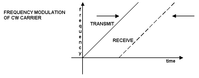
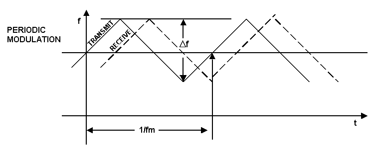
In the receiver, the return signal is heterodyned with a portion of the transmitted signal producing a beat frequency. If there is no Doppler shift (target motion), the beat frequency is a measure of the target’s range. After amplification, this beat frequency is fed to a frequency analyzer for range determination. If there is sufficient target motion, a Doppler frequency will be superimposed on the beat frequency and erroneous ranges will be measured. To determine the true beat frequency and thus the true range, the Doppler frequency must be taken into consideration.
When more than one target is within view of the radar, the mixer output will contain more than one difference frequency. If the system is linear, there will be a frequency corresponding to each target. To determine individual target ranges, the individual beat frequencies must be separated from each other. This can be done with filters or other devices that complicate the radar. Since this adds significantly to the cost of the FM-CW radar, most do not have them incorporated. If the system is nonlinear, the problem of resolving targets and measuring the range of each becomes even more complicated. FM-CW radar is mainly used as an altimeter, an application for which there is only one target, the earth.
PULSE MODULATED RADAR
This class of radar systems covers most of the radars in use today. It includes conventional pulsed radar, pulse Doppler radar, and pulsed-moving target indicator (pulsed–MTI) radar.
Conventional Pulsed Radar
The simplest pulsed radar system consists of a pulse generator, transmitter, receiver, antenna, display device, and a timing circuit. The receiver and transmitter are isolated from each other by a switching circuit. The receiver is connected to the antenna as long as possible to look for a returning signal. Since the antenna is shared, the radar cannot receive any target returns whenever the antenna is switched to the transmitter. Conventional pulsed radar provides the following types of information:
Pulse Doppler Radar
A pulse radar determines the speed of moving targets by measuring the Doppler frequency shift in the return signal. The pulse Doppler radar consists of the same components as conventional pulse radar with the addition of a CW oscillator. Like the conventional pulse radar, the pulse Doppler radar can determine presence of target, range, and direction to target. Additionally, with the aid of the CW oscillator, the speed of the target can be computed. The speed of the target is determined by comparing the frequency of the return signal to the transmitted signal. However, when the speed of the target causes a Doppler frequency equal to a multiple of the PRF, the radar cannot resolve the target’s speed. Such speeds are termed blind speeds. To avoid this problem, the Doppler radar has a high PRF that avoids blind speeds, but high PRF causes ambiguities in range. Pulse Doppler radars are frequently used as airborne intercept, missile seeker, and fire-control radars.
Pulsed-Moving Target Indicator Radar
The main difference between a pulse Doppler radar and an MTI radar is the desired information. Desired information from a pulse Doppler radar is the speed of the target. The PRFs are selected so as to avoid having blind speeds near the target’s expected speed. For pulsed-MTI radars, the desired information is the detection and range of the target even in the presence of background clutter. In the pulsed-MTI radar, the PRF is chosen low enough to provide much longer unambiguous ranges than the PRF of a pulse Doppler radar but results in blind speeds and a frequency measurement that is ambiguous. MTI radars, therefore, detect moving targets but do not measure target speed. Pulsed-MTI radars are often used as air surveillance radars.
An MTI radar compares the phase of the target return to the phase of the previous target return and detects any difference in the two signals. The radar stores a sample of each target return for a time equal to the PRI. Each target return travels over two signal paths in the receiver. One goes directly to the phase detector and then goes to the canceler circuit where it is compared with the stored copy of the previous return. The second goes through the delay line to the compression circuit. The delay is such that the target return appears at the end of the delay line just as the return from the next pulse arrives at the canceler circuit.
For the MTI radar to compare the phases of the target return signals, it must have a transmitted signal that is phase stable, or coherent, with respect to some reference. The MTI system maintains coherence by the use of a reference oscillator. If a power oscillator (e.g., a magnetron) is used, the phase of the reference oscillator is locked to the phase of each transmitted pulse. When a coherent oscillator (COHO) is used, the transmitted signal is produced by keying a highly stable signal from the continuously running COHO.
TYPES OF RADAR
No single radar effectively combines the functions of search, acquisition, tracking, and missile guidance. Therefore, radar systems are designed to perform specific functions. See table 1-4. Note that in addition to its purpose or function, a radar system must be designed to meet other limitations that are not necessarily function-related. Some of these limitations are size, weight, power requirements, frequency band limitation, and platform types. As a result, a radar complex or a modern warship has several radars tailored to fit the defense requirements.
Table 1-4.— Radar PerformanceRADAR FUNCTION |
OPERATIONAL RANGE |
MAXIMUM UNAMBIGUOUS RANGE |
RANGE RESOLUTION |
EARLY WARNING |
250-800 KM |
500-960 KM |
1-2 KM |
ACQUISITION |
100-400 KM |
100-450 KM |
1-2 KM |
TRACKING |
SHORT RANGE |
40-80 KM |
45-140 M |
FIRE CONTROL |
30-60 KM |
60-90 KM |
45-120 M |
METEOROLOGY |
300-500 KM |
150-600 KM |
15-60 M |
MAPPING |
5-200 KM |
50-150 KM |
15-120 M |
SEARCH RADAR
The search radar is designed to give warning of approaching targets. Search radars typically use circular, sector, or electronic scans. The search radar may be limited to a single dimension, range only; or may be capable of two dimensions (2D), bearing and range; or three dimensions (3D), bearing, range, and elevation. Other characteristics of the search radar are low illumination rate, large scan volume, and high transmitter power. Examples of search radars are early warning (EW), surface search, airborne search, navigation, and height finder.
Early-Warning Radar
The primary function of the early-warning (EW) radar is to alert the defense forces of approaching targets as early as possible. This radar function is also termed long-range search. Critical operational features of an EW radar are range and power. Also, an EW radar should resolve the position of the target within a reasonable margin of error. However, the accuracy of range and bearing should not be sacrificed at the expense of maximum range. Therefore, EW radars are normally designed with high power, wide beam angles, fairly long pulse duration, and low PRF. Since it is unnecessary to frequently update the position data on a long-range target, relatively slow circular scans are used. In effect, this slow scan enables a greater number of pulses to illuminate the target, thus providing a better chance of detection at great distances. The nature of the terrain is also important. In rugged mountain areas, the EW radar would be situated to provide maximum coverage. Since mountain ranges produce "blind spots" or gaps in coverage, additional EW radars are required to cover these areas. These radars would be linked to the main radar site by communications links. An EW radar site usually has a separate height finder to refine target position if the EW radar does not have 3D capability. The maximum operational range of an EW radar is usually between 400 and 800 kilometers (kms), but may extend to extremely long ranges. Typical EW radars would have the following parameters:
Ballistic Missile Early-Warning Radar
The ballistic missile EW (BMEW) radar, a subcategory of the EW radar, detects ballistic missiles in mid-trajectory at ranges of 3000 to 15,000 kms and at altitudes of 1000 to 2000 kms. The BMEW also monitors satellite trajectories for monitoring orbital decay of satellites and the estimated time that a satellite will remain in orbit. Typical BMEWS radars would have the following parameters:
Over-the-Horizon Radar
Another radar system with extremely long detection ranges is the over-the-horizon (OTH) radar. The curvature of the earth limits the maximum detection range of normal ground-based radar sites. The OTH radar was developed to overcome this problem. The OTH radar uses the layers of the ionosphere to refract the radio waves, enabling it to detect and track targets beyond the radio horizon. The OTH radar can detect aircraft, missiles, and ships, as well as nuclear explosions, earth surface features (e.g., mountains, islands, and cities), seas, auroras, meteors, and satellites. The following are two types of OTH radars:
Back scatter—Uses the same radar to transmit and receive. The signal is radiated up to the ionosphere where it is refracted. The target is detected when the signal reflects off of it and is re-radiated up to the ionosphere where it is again refracted to the radar antenna.
Forward scatter—Uses a transmitter and receiver that are spaced far apart. The signal is radiated up to the ionosphere where it is refracted back to earth. It reflects from the earth and strikes a target. The energy from the target changes direction and continues to radiate until it reaches the receiver.
Typical OTH radars would have the following parameters:
Surface Search Radar
The primary function of a surface search radar is the detection and determination of accurate range and bearing information of surface targets and low-flying aircraft. Surface search radars maintain a 360° search pattern for all objects within line-of-sight (LOS) from the radar antenna. Search radar information can be used as an input to the weapons system. Shipboard surface search radar is also used extensively as a navigation aid in coastal waters and in poor weather conditions.
The maximum range ability of a surface search radar is primarily limited by the radar horizon LOS. Higher RF permits maximum reflection from small target reflecting areas, such as ship masthead structures and submarine periscopes. Narrow pulse duration permits a high degree of range resolution at short ranges and has greater range accuracy. High pulse repetition rates permit maximum illumination of targets. Appropriate peak powers permit detection of small objects at LOS distances. Wide, vertical beamwidths, usually between 12° to 16°, permit
compensation for pitch and roll of the ship and detection of low-flying targets, while narrow, horizontal beamwidth, approximately 1.5° , permits accurate bearing determination and good bearing resolution. Typical surface search radars would have the following parameters:
Air Search Radar
This radar detects and determines the range and bearing of aircraft within a 360° surveillance area. The maximum range can exceed 300 miles. Air search radars typically use low RF to permit long-range transmissions with minimum attenuation. Wide PD and high peak power is used to aid in detecting small objects at longer ranges. Low PRFs provide for greater maximum ranges. A wide, vertical beamwidth is used to ensure detection of objects from the surface to relatively high altitudes and to compensate for the pitch and roll of the ship. Medium horizontal beamwidths provide fairly accurate bearing information.
In addition to providing range and bearing information, some air search radars also provide height information for air contacts. These three-dimensional (3-D) radars provide range, bearing, and altitude information. Two-dimensional (2-D) radars provide only range and bearing information. Air search radars are used to provide early warning and to guide combat air patrol (CAP) aircraft to intercept enemy aircraft.
Navigation Radar
The primary mission of a navigation radar is to guide an aircraft or ship from one location to another. Used to keep them from colliding with other obstacles, navigation radars also permit operations in less than optimal weather and enable the pilot to navigate by instruments. Navigation radars provide continuous information as to a pilot's position with respect to a desired course, his proximity to other craft and ground obstacles, and miscellaneous meteorological information. Since navigation radars on aircraft or ships provide only a part of the information needed, other navigational aids (e.g., beacons) are necessary to provide safe travel.
Airborne navigation radars perform many functions. They are used for terrain avoidance or terrain following. The weather avoidance radar aids the pilot in avoiding areas of unfavorable weather. Although it may not always be thought of as a radar, the radio altimeter is used as a navigational aid.
Shipborne navigation radar is also used for enhancing the safety of ship travel by warning of potential collision with other ships and for detecting navigation buoys, especially in poor visibility. Automatic detection and tracking equipment is available for use with radar for the purpose of collision avoidance. Shore-based radar of moderate resolution is also available for the surveillance of harbors as an aid to navigation.
Global navigation systems are a great aid to navigators to keep their craft from becoming lost or allowed to stray into restricted areas. Nearly always, aviation uses short-range radio navigation aids such as very high frequency (VHF) omnidirectional range/distance measuring equipment (VOR/DME). Marine uses include non-line-of-sight radio systems such as LORAN-C, Decca, and Transit. These systems aid in position determination of the craft with a relatively high degree of accuracy.
Height Finder Radar
Height finder radars provide altitude information about airborne targets and are normally co-located with EW radars. The height finder radar uses a fan beam that is wide in the horizontal plane and narrow in the vertical plane. By moving (or scanning) this beam vertically, the radar measures the elevation angle and range of a target. The height finder radar can be scanned in elevation mechanically by physically moving the feed point or the entire antenna assembly, or by electrically positioning the beam through the use of electronic phase shifters. The range of this radar is generally about 150 to 450 kms and provides an elevation sector of between 0° and 60° . Typical height finder radars would have the following parameters:
ACQUISITION RADAR
The acquisition function usually occurs following the search mode after a target is detected. The acquisition radar takes a specific target and performs fine grain measurements of target range, azimuth, elevation, and speed to hand off to a target tracker radar without further search. During the handoff from the search radar to the acquisition radar a change to a higher RF occurs. The target acquisition radar generally has an operating range of
100 to 400 kms and an azimuth resolution of 01° . Other characteristics include higher target illumination rates, smaller search volume, and moderate transmitter power. Typical scan patterns for an acquisition radar are circular, sector, and raster scans. Other scan patterns that can be used are spiral, helical, palmer, and nodding scans, though they are not often used.
Acquisition radars cover short to medium ranges and serve as position indicators for other radar sets. Examples of acquisition radars are Ground Control Approach/Precision Approach, Ground Control Intercept, Coastal Surveillance, and Ground Surveillance.
Ground Control Approach/Precision Approach Radar
The ground control approach (GCA) radar is a short-range acquisition radar used to provide control of aircraft in the vicinity of an airfield. The range of this radar is generally between 30 and 260 kms. The scan is a circular scan of 2 to 10 SPS. As the aircraft approach within approximately 35 kms of the airfield, the precision approach radar (PAR) takes over. This radar obtains data on the position of aircraft relative to the runway and guides the aircraft to a safe landing. This system is extremely helpful in bad weather. The PAR has a range of up to 35 kms and has a circular scan of less than 2 SPS.
Ground Control Intercept Radar
The Ground Control Intercept (GCI) radar is similar to, and can function as, an EW radar; however, the parameters of the GCI radar have a shorter maximum range. Usually located at military airfields, the GCI radar site provides target position information to vector defense aircraft to hostile targets. The parameters of the radars in this category are generally selected so that a compromise results between the range of the radar and the accuracy of the control system. The range of the GCI radar is typically 200 to 400 kms. Typical GCI radars would have the following parameters:
Coastal Surveillance Radar
The coastal surveillance (CS) radar provides information about ship movement for either coastal defense or ship movement control. A height finder radar may be co-located to provide information on aircraft.
Ground Surveillance Radar
There are two basic types of ground surveillance radars: the battlefield surveillance (BS) radar and the mortar locating radar (also known as the shell-tracking radar). The BS radar detects and locates enemy vehicles, weapons, and personnel in the immediate area. The mortar locating radar determines the location of enemy weapons by tracking their projectiles. Mortar locating radars provide inputs to direct return fire and are, therefore, called field artillery radars.
BS radars are divided into medium-range radars with a detection range for large targets (e.g., moving trucks or tanks) of 15 to 20 kms. These radars are installed on trucks or trailers, while short-range radars are transported or carried in manpacks. Medium-range BS radars can detect traffic by detecting dust, smoke, or heat given off by vehicles. The battalion or equivalent units use this class of radars. Short-range ground reconnaissance radars usually have a maximum detection range of 5 to 10 kms and detect targets as small as an individual soldier. Radars of this type are used by companies, platoons, and reconnaissance patrols, as well as guard posts. Short-range radars generally use a manual or steady scan and are capable of detecting only moving targets by relying on the Doppler effect.
Mortar locating radars must have a greater range and tracking capacity than surveillance radars. These radars are used by division artillery or in artillery reconnaissance units. This type of radar tracks the flight of the trajectile and uses this data to compute the actual position of the mortar or launching vehicle. Mortar locating radars generally use a conical scan or a unidirectional sector scan and have a maximum detection range of 10 to 30 kms.
TRACKING RADAR
The tracking function follows the acquisition mode and the RF usually stays the same. Tracking radars provide continuous positional data on a target and are designed to precisely locate targets and track location of the target for possible input into weapon systems. Since these radars are designed for shorter ranges, the output power is lower. Radars of this type are characterized by short emitter times, small target illumination rate, and small scan volume. A tracking radar system provides range, speed, and angle to achieve fine-grain positional data that may be used to determine the path and future location of the target. Two types of tracking radars are the continuous tracking radar and the track-while-scan (TWS) radar. The continuous tracking radar provides tracking data on one target, while the TWS radar can supply sampled data on more than one target.
The continuous tracking radar uses various methods for tracking its target such as lobe switching, conical scan, and monopulse between two or more positions. A TWS radar develops tracks on numerous targets that it has detected on a scan-to-scan basis. Target position and angle of movement information are then placed into a computer system to start a track on the target. One type of TWS radar uses beam position, usually in a raster scan, to track a target. By revisiting a certain area with the beam at irregular time intervals, a track of the target can be accomplished.
The tracking radar must first find the target before tracking is initiated. Some radars operate in an acquisition (search) mode in order to find the target before switching to a tracking mode. Although it is possible to use a single radar for both acquisition and tracking functions, this usually results in operational limitations. When the radar is used for tracking, it usually cannot detect other potential targets. Therefore, many tracking systems use a separate search radar to provide the tracker with the target position. A search radar, when used for this purpose, is called an acquisition radar. The acquisition radar designates targets to the tracking radar by providing the coordinates where the targets are to be found.
A tracking radar's range is generally short and limited to the range of its corresponding weapons system. Range resolution is on the order of a fraction of a kilometer and with an azimuth resolution of l° . Typical tracking radars would have the following parameters:
FIRE-CONTROL RADAR
Normally fire-control radars are used with unguided weapons such as antiaircraft artillery to direct weapons fire toward a target. After a tracker radar has achieved lock, a fire-control solution can be determined. The fire-control radar must then acquire and track the target for the purpose of destroying it. The fire-control radar is an integrated part of the weapons system and will, generally, be as mobile as the associated system. In a fire-control system, maximum range is secondary to accuracy. The range of fire-control radars exceeds the range of the associated
weapons to allow for acquisition and tracking prior to weapon engagement. Ranges of 30 to 60 kms with a tracking resolution of 100 meters are typical. The fire-control radar usually requires separate scan modes to locate and track the target. The acquisition modes most often used are raster and sector scans. Track modes include conical, lobe switching, and passive scan techniques.
The target illuminator is used to radiate a target with sufficient energy to permit a missile to home in on the reflection. These emissions are normally CW with little or no modulation. Using other inputs (target trackers), the emitter will automatically be positioned on the target. Passive or active tracking scans are also employed for illumination.
MISSILE GUIDANCE RADAR
A radar that provides information used to guide a missile to a hostile target is called a guidance radar. A typical missile guidance signal has a medium to high RF, low to high PRF, a narrow PD, and may have a steady scan or no scan. Other characteristics include a small target illumination rate, small scan volume, and pulse compression. Missiles use radar to intercept targets in three basic ways: radio command control, radio remote guidance, and homing guidance.
Radio Command Control
In this system, data transmitted to the missile from an outside source controls and guides the missile. This method is characterized by missile movement control originating at the control point. The commands formed are transmitted to the missile over a radio command link. This command link usually incorporates two channels for movement control in two planes—pitch and yaw. Information about the target and the missile positions are required at the control point. To acquire this information, most control points have two radars, one that tracks the missile and one that tracks the target. The missile radiation sensor operates in the interrogation-response mode by carrying a beacon onboard. This system provides better tracking because the beacon returns a larger signal to the radar. A disadvantage is that it can guide only a limited number of missiles at one time and may easily become saturated with targets. When the control point is the launch point (airborne platform), the target and missile sensors are the same. The three common types of pulsed command guidance signals are as follows:
Radio Remote Guidance
This control method is characterized by the generation of commands onboard the missile. The most common form of this method is the beamrider. The missile follows a beam (radio, radar, or light) to the target. Equipment is contained within the missile to determine its position relative to the center of the beam and to maintain its position in the center of the beam. The most common type of beam used is a radar emission. An advantage of the beamriding system is the relative simplicity of the guidance equipment in the missile. However, as a separate guidance beam is required for each target, the system can easily become saturated with enemy targets. With beamriding guidance, more than one missile can be guided with one radar if the missiles are launched sequentially.
Homing Guidance
This control method is characterized by generation of commands onboard the missile in accordance with the movement of the target relative to the missile. In this system, a sensing device in the missile responds to some form of energy radiation from the target. Once the missile is close enough for the sensor to respond to this radiation, the missile will seek out or home in on the target. The energy that the missile homes in on can be electromagnetic, heat, light, or sound. The three general types of homing systems are as follows:
Active homing guidance—Both the source of energy to illuminate the target and the receiver of the energy reflected from the target are carried in the missile. The missile is completely independent once homing starts; the launch platform can concentrate on another target.
Semiactive homing guidance—The transmitter that illuminates the target is located externally, and a receiver that locates the target and computer that predicts the future position of the target are carried in the missile. The missile is not independent from the launch platform.
Passive homing guidance—The missile uses the energy radiating from the target to direct itself to the target.
IDENTIFICATION, FRIEND OR FOE RADAR
Identification, friend or foe (IFF) is a radar beacon system designed to identify an airborne platform as a friendly or unknown aircraft. The IFF system consists of an interrogator and a transponder subsystem. An IFF system normally operates in conjunction with a parent radar. The pulses transmitted by the IFF interrogator are synchronized with those of the aircraft search radar (parent radar), and the IFF antenna is mounted on the search radar’s antenna.
IFF is similar to conventional radars except that the receiver processes a signal radiated from a transmitter and returned by the target rather than the energy returned by the target. An aircraft’s IFF system transmits interrogating pulses to which transponders carried in all friendly aircraft respond with coded replies. This results in the challenged transponder providing location and coded information in the returned RF pulse. The received coded RF pulses are converted into decoded video for display.
Advantages to IFF include enhanced target returns, a means of target identification, and a way to provide information about the target to the radar. Since there is only a one-way path from the interrogator to the transponder and from the transponder to the interrogator, the output power of both transmitters remains relatively low while achieving acceptable performance. Separate transmitting and reply frequencies eliminate ground clutter and weather return problems. Dependence upon target size (as with a radar echo signal) is virtually eliminated. Finally, data can be included in the interrogation and reply process, thereby providing target identification, altitude readout, fuel remainder, as well as other information.
Disadvantages to IFF include interference from other beacons, especially in areas of high traffic density. If there are too many beacons located within a given region, the interference may be high enough to render the IFF useless. If a continual stream of interrogations is received, a transponder can develop a condition known as over interrogation and shut down. To compensate for a dense environment, a transponder can use a dead-time circuit. During this dead time, incoming interrogations are ignored. Three other disadvantages are as follows:
Fruit. An interrogator receives replies initiated by other interrogators in the area. If they are received in sync with the radar sweep, they will be presented at different positions all over the radar display.
Garbling. Replies from several different transponders arriving at a single interrogator may cause the code to be misinterpreted or rejected. It can also occur at the transponder when several different interrogations are present in the receiver at the same time.
Ring around. Ambiguities occur when targets are interrogated by side lobes of the IFF. The side lobe returns arrive at the interrogator and radar at the proper time and are mistaken for replies from targets in the main beam.
IFF uses three interrogation methods: Active Interrogation, Independent Interrogation, and Combined Interrogation. These methods are described in the following paragraphs.
Active Interrogation
In this application, the radar signal triggers a transponder onboard the target. The transponder re-radiates a replica of the radar signal on the same RF. Advantages and disadvantages include the following:
Advantages Disadvantages
Stronger reply pulses
Unnecessary responses
Extended radar range
Overloaded radar output system
Better angular resolution
Wide range of RF frequencies
Independent Interrogation
In this application, the radar signal is sent using a special transceiver synchronized to the radar system. The IFF transponder operates over a relatively narrow frequency band. The interrogation signal is used only when needed, eliminating the repeated responses to the radar illumination. Advantages and disadvantages include the following:
Advantages Disadvantages
Reduced signal density
Less angular resolution
Standardized responders
Interference from other beacons
Narrow range of RF frequencies
Combined Interrogation (U)
In this application, both the IFF interrogation signal and the radar signal must be received simultaneously before the target will respond. When this happens, the interrogation is validated and decoded to determine the type of response required (i.e., identification, altitude, aircraft number, heading, ground speed, etc.). The proper reply is encoded and transmitted on the transponder frequency. Advantages and disadvantages include the following:
Advantages Disadvantages
Positive target identification
Interference from other beacons
Less power
Deadtime gate circuit required
Stronger target signals
METEOROLOGY RADAR
Meteorological radars provide data on the current status of atmospheric conditions and data for flight operations and weapons testing. Meteorological radar may have common parameters with fire-control radar and
search radar. They can measure the speed and direction of wind at various altitudes, locate clouds, detect jet streams in the atmosphere, and detect changes in temperature and humidity. Additionally, these radars aid in locating and tracking hurricanes, typhoons, tornadoes, gales, and other storm-related phenomena. Meteorological radars also play an important role in safeguarding air traffic and in directing antiaircraft missile and artillery fire. The operational range of the meteorological radars varies from 300 to 500 kms. These radars have relatively good range resolution, on the order of tens of meters, and typical angular resolution of 1° to 5° . These radars use waves reflected by the troposphere or from special reflectors or transponders attached to sounding balloons.
MAPPING/IMAGING RADAR
Mapping radars provide surface images with nearly photographic resolution. They are employed in many nonmilitary applications for remote sensing of the environment, mapping of regions of the world under cloud cover too heavy for optical photography, mapping of agriculture, geological exploration, location and density of sea ice, and detecting mineral and oil resources. For military applications, they reproduce replica of ground terrain for navigation and identification of military targets.
To obtain images of the earth's surface or individual targets, high resolution in both range and azimuth is needed. To achieve a good resolution in azimuth, a narrow beam is used. To achieve a good resolution in range, pulse compression is used.
One type of ground mapping radar that achieves very high azimuth resolution is the synthetic aperture radar (SAR). SARs use a coherent RF and the Doppler phenomenon to effectively process returns over a segment of the radar platform flight path. This produces an effectively large (synthetic) antenna and improves the angular resolution. Pulse compression techniques are often used to improve range resolution. High-resolution radars may also use inverse synthetic aperture radar (ISAR) techniques. Instead of depending on the movement of the platform as in SAR techniques, the ISAR depends on the movement of the target with respect to a stationary radar antenna that is constantly illuminating the target. Another type of mapping radar is the Real Aperture Mapper. This radar is also known as the brute force real aperture. Real Aperture Mappers use standard radar techniques to measure the distance to the ground. The pulse duration and beamwidth of the radar, therefore, limits the resolution.
Mapping radars are normally fitted aboard aircraft or satellites. The parameters of mapping radars are matched to the platform performance and intended coverage. Most mapping radars have no active scan; instead they use the platform's motion to move the radar beam along the earth's surface. Also, the angle of incidence must be accounted for when determining the radar's resolution. The satellite mapping radar has the advantage of being able to do mapping in extreme weather conditions and during nighttime hours, when mapping from an aircraft is much more difficult.
RADAR SCAN TYPES
Scanning is the process of searching a large volume of space by moving the antenna or shifting the radiation pattern while looking for, or tracking, a target. The type and method of scanning used depends on the purpose and type of radar and on the antenna size and design. Knowledge of the type of scan used by a radar provides valuable information about the purpose of a radar. As a general rule, scans requiring less than 1 second to complete a full cycle are reported in hertz (Hz) or SPS, and scans requiring more than 1 second are reported in seconds or SPR.
Most radars transmit a continuous pulse train of relatively narrow, high energy pulses shaped into a directional beam by the antenna reflector. The antenna is pointed toward the desired volume of space. When illuminated, any sufficiently large object will return energy to the radar antenna. The returned energy is detected and displayed by the radar. The purpose of the directional beam and the scan motion is to provide azimuth and elevation angle information.
Operational requirements, for example search mode, place restrictions on the maximum scan time. The physical requirements cause the space around the radar to be divided into resolution cells that depend on the antenna beamwidth and pulse duration. The antenna scan rate is normally a compromise between the rate at which target position information is desired (the scan rate) and the data rate (the number of pulses on the target). The slower the scan rate, the more pulse returns and the better the detection capability but the more inaccurate the target position. Increased scan rate reduces the error in estimates of target position, but also reduces the probability of detection.
The beam shape of the radar is formed by the configuration and design of the antenna. The beam shape is one of the parameters that serve as a general indicator of the emitter function. Search radars generally use a fan beam (one that is wide in one plane and narrow in the plane perpendicular to it); target tracking and acquisition radars most often use a pencil beam (one that is of nearly equal beamwidth in both azimuth and elevation). For the pencil beam to be used effectively, the radar must be capable of rapidly aiming the beam in the desired direction. Some search radars employ a pencil beam that is swept electronically in one direction and mechanically in the other, thereby effecting a fan beam in the direction of the swept beam.
The two basic methods of beam scanning are mechanical and electronic. In each method, the beam is moved in various ways as described in the following:
Mechanical
Electronic
NONSCANNING RADAR
A nonscanning radar (often referred to as steady scan) radiates a beam at a fixed point from the radar. Any radar can operate in a nonscanning mode by deactivating the normal scan. Some newer radars transmit a nonscanning beam and track targets by scanning the returning echo with a receiving antenna or feed.
MANUAL OR IRREGULAR SCAN
An irregular radar is any radar with an antenna that is manually rotated to a desired bearing or to search a desired area. The scan period varies according to the rate at which the antenna is manually positioned. The scan can also be steady if the antenna is not moved. Since scan period cannot be determined, it is considered an irregular scan.
CIRCULAR SCANS
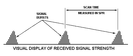
A circular scan is the most common form of mechanical scanning. In circular scanning antennas, the antenna continuously rotates 360° about a vertical axis in either a clockwise or counterclockwise direction. The time between successive signal sweeps is called the scan time. For a circular scan, this time must be constant. If it is not, the scan may be a special case of circular scan or a sector scan. See figure 1-5.
Search radars commonly use circular scans. Long scan times are associated with long-range search and acquisition radars. Medium scan times are associated with ground-controlled intercept and surface search. Fast scan times are associated with airborne navigation or airport surveillance.
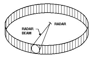
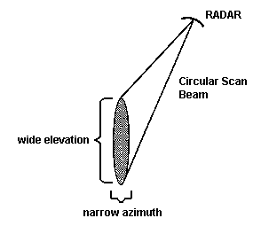
Search type scans, like the circular, normally use an antenna that is wide in the horizontal plane and narrow in the vertical plane. This results in a fan beam that is wide in the vertical plane and narrow in the horizontal plane. See figure 1-6. Some radars have only a circular scan that provides target range and azimuth information. These radars are often co-located with height-finding radars to provide elevation information. Other radars are designed to provide range, azimuth, and elevation information with varying degrees of accuracy in a single radar set by using multiple beams or by superimposing a vertical scan onto the circular rotation.
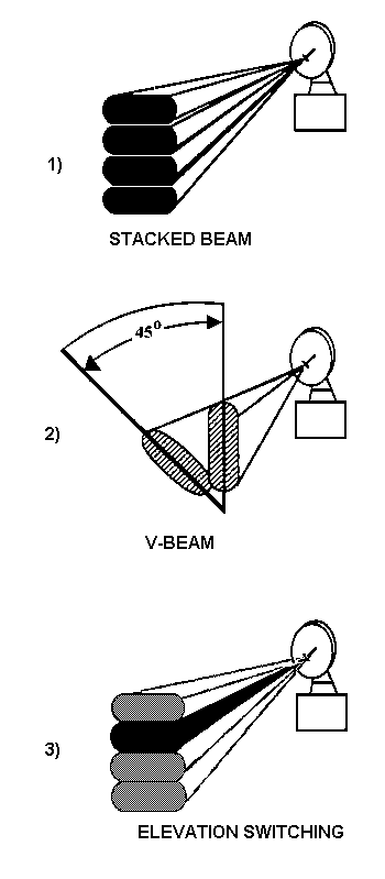
Three standard multiple beam techniques used to determine elevation are stacked beams, V beams, and elevation switching (figure 1-7). Stacked beams consist of several simultaneously transmitted beams at different elevations and RFs. Approximate altitude is determined by correlation of the signal strength at each RF with the beam position at that RF. The V-beam method consists of two fan beams tilted away from each other (usually at a 45° angle). Elevation is determined by measuring the time delay between the return pulses from each beam. Elevation switching is accomplished either mechanically or electrically. Two ways to accomplish electronic changes in elevation are modulating the pulse (intrapulse or interpulse) and using phase steered arrays.
In order to yield accurate bearing information on a distant target, the radar must first have a narrow horizontal beamwidth. Since the same antenna is used for transmitting the initial pulse and receiving the echo, the antenna cannot change its direction too rapidly, or the returning echoes will not be received. In other words, the maximum range of a radar is inversely related to the antenna rotation rate. Therefore, a slow rotation rate is necessary for long-range radars. Radars used for short-range search, small object search, or close navigation will normally use a much faster scan rate or SPR. To determine the SPR, count the number of seconds between the main bursts of the signal. See figure 1-8. Normally, three revolutions of the radar are required to determine the SPR. The more revolutions observed, the more accurate this measurement will be.
The speed of the antenna rotation must be compatible with the PRF and the beamwidth of the radar. To obtain optimum resolution of a target, the scan and beamwidth must allow several pulses to strike each target as the beam crosses. Therefore, the scan period, beamwidth, and PRF are interdependent. The horizontal beamwidth of a circular scan is normally narrow to provide the radar with good azimuth resolution.
SECTOR SCANS
There are two types of sector scans, bidirectional and unidirectional. A bidirectional sector scans back and forth (either horizontally or vertically) through a desired sector. A unidirectional sector scans in only one direction. Sector scans are measured in SPS.
Figure 1-9 shows a visicorder representation of a bidirectional sector signal from three different intercept receiver locations within the beam. A receiving system at intercept positions (B) and (C) will have trouble distinguishing a sector scan from a circular scan. The easiest way to distinguish between the two scan types is to look at the lobe structure on alternate scans. See intercept position (A). The lobe structures are the exact "mirror image" of the preceding lobes.
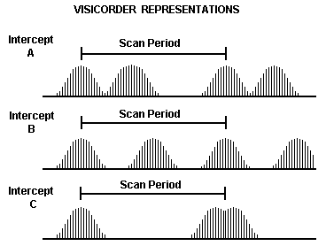
The main identifying feature of a bidirectional sector scan is the uneven or irregular time intervals at which the signal bursts are heard. The signal from a bidirectional sector scan radar is heard three times during each scan period. To determine the scan rate for a sector scan, you time the period in which you hear three successive signal bursts.
To better understand how to measure the scan rate for a sector scan, refer to view A of figure 1-10. As the radar beam moves from the right sector limit to the left sector limit, a signal burst will be heard when the radar beam strikes intercept point A. At this point, start the stopwatch; this is the first burst of the scan period. See view B of figure 1-10. The radar beam continues until it reaches the left sector limit, where it starts back to the right sector limit. As the beam moves toward the right limit, it again strikes intercept point A; this is the second burst of the scan period. The beam continues until it reaches the right limit, then begins back toward the left limit. The radar beam strikes intercept point A; this is the third burst of the scan period. The beam continues until it reaches the right limit, then begins back toward the left limit. The radar beam strikes intercept point A; this is the fourth burst.
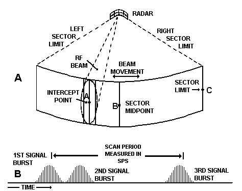
At this burst, stop the stopwatch. The time measured is the scan rate. The time interval between signal bursts one and two is much shorter than between signal bursts two and three. This relationship accounts for the uneven audio intervals that characterize a horizontal sector scan. If the intercept position is located exactly at the sector midpoint or sector limit, intercept point B, the signal bursts will recur at evenly spaced intervals, just as in a circular scan.
Many airborne surface search radars have a fixed sector pattern with the center axis dead ahead of the aircraft. If the scan changes from a sector to a circular sound, this could indicate that the aircraft has changed course and is heading toward you, tracking you on its equipment.
Horizontal Bidirectional Sector Scans
A horizontal bidirectional sector scan sweeps its beam back and forth horizontally through a desired sector. The amount of sector sweep may be either variable or fixed, depending on the radar. The antenna scans in both directions. The horizontal sector provides search and early-warning radars with coverage of a smaller area than that of a circular scan, but the coverage area may be illuminated at a faster rate.
Examples of this scan are airborne navigation, weather avoidance, and target acquisition. Horizontal sector scans are also used for navigation by ships and some coastal surveillance radars. A horizontal bidirectional sector scan normally has a scan period of 1 to 5 seconds.
Vertical Bidirectional Sector Scans
A vertical bidirectional sector scan sweeps its beam back and forth vertically through a desired sector. The antenna scans in both directions. The vertical sector is commonly used for height finding. Vertical sector scans operate and are measured in the same fashion as horizontal sector scans. The only difference is that the radar antenna moves up and down for the vertical sector scan, instead of back and forth horizontally. A vertical bidirectional sector scan typically has periods of 2 to 4 seconds.
Many land-based, height-finding radars use the vertical bidirectional sector scan with antennas that mechanically move or nod in an up and down motion. In some cases, the antennas rotate in a circular pattern while simultaneously nodding. The scan audio heard in these instances would be the same as that associated with a circular scan.
Unidirectional Sector Scans
A unidirectional sector scan radar moves its beam through a desired sector, usually at a high rate (i.e., from 10 to 50 Hz). These scans can be horizontal or vertical. However, since an ES operator cannot determine the plane of orientation, all unidirectional sector scans are usually classified "plane undetermined." The unidirectional sector scanning radar produces a rapid scan by electronically shifting through a series of multiple feeds or by rapid rotation of a single feed (figure 1-11). The beam is reflected from a fixed antenna. The entire antenna can be rotated to change the area being scanned or to follow a detected target. As the name unidirectional implies, the scan is moved in one direction, unlike the bidirectional which reverses direction at the end of the scan limit. The unidirectional scan is used when the radar must provide rapid and precise location updates on fast-moving targets. The unidirectional scan can be differentiated from the circular or sector scan by its high scan rate (usually greater than 10 Hz) and the absence of back lobes.
ORTHOGONAL SCAN
An orthogonal scan (often referred to as a track-while-scan) has two separate unidirectional or bidirectional scans, one in the vertical and the other in the horizontal plane. The beam swept horizontally is wide in the vertical dimension, and the beam swept vertically is wide in the horizontal dimension. An orthogonal scan using bidirectional scans may either interlace the scans (i.e., one horizontal sweep, one vertical sweep, the opposite horizontal sweep,
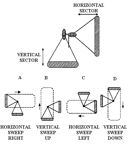
followed by the opposite vertical sweep) or simply complete the vertical bidirectional scan and then the bidirectional sector scan (figure 1-12). The horizontally scanned beam provides azimuth data, and the vertical scan provides the radar with elevation data. Targets are tracked in both azimuth and elevation without interruption of the search scan.
An orthogonal scan can track several targets at the same time and is most commonly associated with airport precision approach systems.
The orthogonal scan appears as two unidirectional or bidirectional scans. The scan should be measured between points on similar lobes of consecutive scans. An orthogonal scan normally has a scan period comparable to those of a sector (i.e., 1 to 5 seconds). The terms "Greek Cross" or "track-while-scan" also refer to the orthogonal scan.
CONICAL SCAN
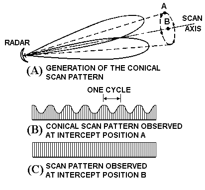
A conical scan rotates a feed horn about an axis within a parabolic dish in a circular motion at a rapid rate, usually from 10 to 100 Hz. See view A of figure 1-13. This type of scan is usually associated with target tracking and gun-laying radars, and is widely used for fire control. A conical scan can be superimposed on other scan types.
There are two basic mechanical methods used to generate a conical scan, nutated feed system and rotated feed system. Both of these methods require the feedhorn to rotate at an offset around the boresight of a parabolic antenna. Differences in the two methods are as follows:
Nutated feed. Maintains a fixed plane of polarization as it rotates. The signal output consists of a beam with the polarization remaining constant.
Rotated feed. Rotates the feed system at an offset from the cone axis. The signal output consists of a beam with the polarization continuously constantly.
Tracking with a conical scan is achieved by sampling the amplitude of the return. When constant amplitude is maintained, the target is in the boresight of the emitter. If amplitude differences are detected, the radar reorients the beam toward the stronger return. The conical scan rate is determined by measuring the time between adjacent peaks and inverting the number to obtain the number of cycles per second, expressed in Hz.
If the position of the intercept station is off the axis of rotation, the intercept antenna will be illuminated with pulses of varying amplitude as the beam rotates. See figure 1-13, view B. The intercept operator can often recognize a conical scan by the harsh, low frequency tone (warbling sound) that is present with the higher tone of the PRF. When the radar is pointing directly at, or is locked on the intercept station, no variations in pulse amplitude are observed. The intercept operator hears only the PRF tone of the radar. See view C of figure 1-13.
Conical-scan-on-receive-only (COSRO) scan, discussed later in this topic, is a technique in which only the received radar beams are scanned. The transmit element is held steady. For COSRO, the electronic warfare support measures (ES) operator will observe only a steady scan.
RASTER SCAN
A raster scan covers a rectangular-shaped sector by scanning back and forth while changing level (angle of elevation) after each sweep. Raster scans are either horizontal raster or vertical raster. There are two primary types of scanning motions used in creating a raster scan, unidirectional and bidirectional. In both methods, each sweep of a sector by the radar beam is referred to as a bar. The unidirectional raster sweeps across a complete bar then returns to the beginning of the bar where it changes the scan elevation (or azimuth) and sweeps another bar. The bidirectional raster sweeps across a complete bar, changes the scan elevation (or azimuth), and sweeps another bar in the opposite direction. In both the unidirectional and bidirectional raster scans, a raster frame contains two
or more bars. Six and eight bar raster frames are common. The pattern of the bars ensures total coverage of a desired area. At the end of a frame (raster pattern), the radar beam returns to the starting position and resumes the raster scan. This time between the end of the frame and the beginning of the next frame is called the flyback time. The bars do not have to be scanned sequentially (i.e., highest to lowest), and one bar may be scanned several times prior to completion of a frame (figure 1-14). The raster scan is used for intensive search of a small rectangular area. Raster scans are used by airborne intercept radars; airborne fire-control radars often use raster scans for search and acquisition.
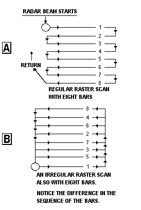
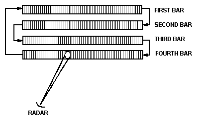
Raster scans are classified in accordance with the number of bars and the number of levels (elevation or azimuth). For example, one scan might be described as a four-bar/four-level horizontal raster as shown in figure 1-15. Each bar occurs on a different elevation level. Another scan might be termed a four-bar/two-level horizontal raster. In it, two bars occur on each elevation level.
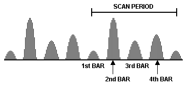
The scan period for a raster scan is the time required to complete a frame (sweep through all the bars). See figure 1-16. The scan rate (illumination rate) is the number of bars swept per second and is the inverse of the scan period. The bar rate is computed by dividing the number of bars the radar scans by the scan period. A raster scan normally has a scan period of 1 to 6 seconds, with individual bar periods of 1 second or less.
PALMER SCAN
A palmer scan is a conical scan superimposed on a circular, sector, or raster scan. The addition of the conical scan gives the radar more uniform coverage and can be used for tracking once acquisition is accomplished. A palmer scan will have the same amplitude characteristics of both scans. The most common type of palmer scan is the palmer raster. Several airborne fire-control systems use the palmer raster for performing search functions. See figure 1-17. In this system, there is a continuous conical scan; in addition, the antenna mount is rotated alternately in azimuth and in elevation.
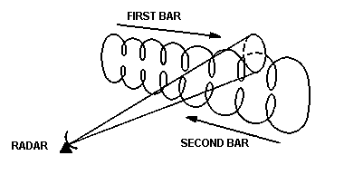
The palmer scan measurement of scan rate involves two measurements: conical (Hz) and the type scan on which it is superimposed. The normal range for the conical portion of this combination scan is usually between 20 and 70 Hz.
HELICAL SCAN
A helical scan is a circular scan in which the elevation angle changes in steps. It is a combination of a circular scan and a vertical sector scan. It is used by land-based mobile units to search a large portion of the surrounding sky area with a narrow, fire-control radiation beam for aircraft targets. The antenna is continuously rotated in azimuth, while it is slowly raised or lowered in elevation. See figure 1-18. When the uppermost elevation is reached, the beam is immediately re-oriented to the original azimuth and elevation. The method used for the beam retrace determines the name of the type of helical scan. If the elevation angle increases to a peak then flies back to the starting point, the scan is a sawtooth helical. If the elevation goes up to its peak then back down in the same pattern, the scan is a sinusoidal helical. Usually a maximum of five or six different elevations can be used by a helical scan and still allow data update from each elevation angle within a reasonable amount of time. Upon locating a target, the system is usually switched to a tracking mode of operation, such as a conical scan.
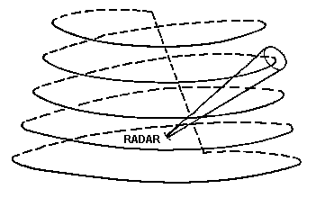
A signal from a radar using a helical scan sounds very much like a circular scan. The difference between the two is the signal amplitudes of a helical scan burst vary periodically, the circular does not. The distinguishing feature of the helical scan is the stepped change in the amplitude over several scans. The amplitude of each burst gets progressively stronger and then weaker as the radar antenna changes its elevation across your position. The helical scan normally has a scan period of 10 to 60 seconds with rotation periods of 2 to 20 seconds per 360° . Measuring scan rate involves two measurements, the circular scan rate in SPR and the framing rate in seconds.
SPIRAL SCAN
A spiral scan is a special case of conical scan. The axis of the radar beam varies its angle with respect to the antenna boresight axis in either a sawtooth manner or sinusoidal manner. After completing a full rotation, the angle between the beam and the fixed axis is increased. Starting from the center, the beam spirals outward until it reaches a maximum desired angle and then rotates back to the center. See figure 1-19. The spiral scan is used by older airborne radars for target acquisition and fire-control radars. When the target is acquired, the system switches to a conical scan. If the target is lost while in a conical scan, the system may automatically switch back to a spiral scan to reacquire the target.
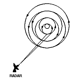
The spiral and helical scans can be confused, but they are different in the following ways:
Spiral Scan. Describes a cone in space with the signal source at the point of the cone. Decreases (and increases) the angle smoothly and continuously. Used by airborne radars.
Helical Scan. Describes a cylinder in space with the signal source in the bottom center of the cylinder. Changes elevation in steps. Used by ground-based radars.
The scan rate, often called the framing rate, is measured in Hz, the same as in conical scanning. A spiral scan usually has a scan period of 1 to 5 seconds with a concurrent rotational rate of 20 to 60 Hz. The number of different amplitude levels observed can often be associated with a specific radar.
LOBE-SWITCHING SCAN
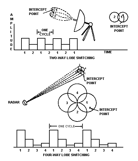
A lobe-switching scan uses two or more overlapping beams of equal amplitude to scan an area. See figure 1-20. The system switches between elements at a fast rate. Normal switching rates are 4 to 50 Hz. Target information is gained by comparing the amplitude of the target return at each antenna/element. This system keeps the radar centered on the target by comparing the strength of target returns from each beam. When four overlapping beams are used, the technique is called four-way lobe-switching.
Four-way lobe switching gives angular accuracy in both the horizontal and vertical planes at the same time. It is considered a precision radar and is usually used for such applications as fire-control and airborne intercept.
If the receiving site is in the exact center of either a two-way or four-way lobe-switching radar, there would be no amplitude change and the scan would appear as steady and the intercept operator would hear the PRF tone. If the receiving site is not located in the exact center, it will receive unequal energy from each of the lobes and the intercept operator will hear chatter in the earphones. The scan rate of lobe switching is measured the same as the conical scan rate one complete cycle through each of the lobes, whether two or four.
SCAN-ON-RECEIVE-ONLY
The scan-on-receive-only (SORO) radar transmits a nonscanning beam. The receiver antenna or feeds are scanned or sampled in elevation and azimuth to perform target tracking and acquisition. The receiving antenna is doing the scanning, not the transmitting antenna. This process prevents a sampled scan pattern from being duplicated and then returned as a decoy by a hostile jammer. This type of scanning technique is virtually impossible to detect by an intercept operator since the scan appears to be steady.
There are four basic types of SORO: lobe-switching-on-receive-only (LORO), conical-scan-on-receive-only (COSRO), monopulse, and hybrid monopulse. Both LORO and COSRO can often be identified by the weak
amplitude modulation (AM) on the scan pattern. This modulation, which represents the scan rate, is caused by the rate at which the receiving feeds are activated (LORO) or the rate of the nutation of the receiving antenna (COSRO). Monopulse exhibits no apparent modulation. Hybrid monopulse may reflect some amplitude phenomenon, but at a lower amplitude than LORO or COSRO.
Lobe-Switching-on-Receive-Only
Lobe-switching-on-receive only (LORO) radars consist of two, three, or four separate receive antenna feeds, each alternately sampling the echo at different angles from the boresight. Sampling rates for a LORO radar typically range from 4 to 50 Hz, depending on the PRF.
Conical-Scan-on-Receive-Only
Conical-scan-on-receive-only (COSRO) radars consist of a transmitting antenna with a separate antenna receiving feed rotated about the boresight of the antenna beam. The receiving feed is typically rotated from 20 to 60 Hz, depending on the PRF.
Monopulse
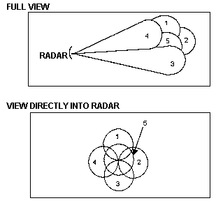
Monopulse radars (figure 1-21) use only one pulse for target tracking and employ five separate antenna feeds, one radiating and four receiving. Modern monopulse systems use one antenna with multiple feeds. The transmitting antenna feed transmits a single pulse. When a pulse strikes the receiving antenna feeds, the relative amplitude at each feed is determined. If the target is in the boresight of the emitter, the receiving feeds will detect the same amount of amplitude. When the receiving feeds register different amplitudes, the angle of the beam is re-oriented until the target is in boresight. This method allows the monopulse radar to calculate angular measurements on the basis of a single pulse vice four or five pulses for conical- and lobe-switching scans. Monopulse radars are also less susceptible to jamming.
Hybrid Monopulse
Hybrid monopulse systems implement monopulse tracking with divider circuits that are sampled internally. These schemes reduce the number of other specialized circuitry required, reducing cost and increasing reliability. The passive scan rates may become evident in the transmitted pulse train.
ELECTRONIC SCANS
In electronic scan systems, the beam direction is controlled electronically and is moved nearly instantaneously from one position to another. Antennas that rely on mechanical scans cannot provide rapid shifts in the beam position. With mechanical scans, there is a practical limit on how fast a system can scan and what the radiated scan pattern can be. There is no such limitation imposed on an electrical scan system since its beam position is controlled by electronic means. Electronic scan systems pose more serious problems for the analyst than the mechanical scan systems. The characteristics of electronic scans determine the information available for scan analysis.
An array antenna must be used to accomplish electronic scanning. Array antennas that perform electronic scanning search in one or more directions without physically moving the antenna. An array antenna is a large number of simple antennas, usually dipoles or horns, each serving as an array element and operating together under some form of mutual control. The elements in an array antenna are arranged in front of the reflector and are identical for easier beam steering. The shape of the array is one of the important factors in determining the azimuth and the elevation scan possibilities as well as the shape of the beam. The transmitted beam is formed by phase addition and subtraction and by amplitude addition and subtraction. By controlling the amplitude and phase of the signal fed to each element in the array, narrow beams are formed. Varying the phase, and possibly the amplitude, of the signal input to the array element causes the individual radiation patterns to coincide in phase in some desired direction, thus "steering" the beam. The antenna beam can be steered as fast as the phase and amplitude of the signal at each array element can be adjusted. Usually the primary method of control is by phase changes, with amplitude variations used to shape the side lobes. Thus, these antennas are called phase array antennas and the array configuration can be one of several geometric shapes. Some commonly used configurations are linear arrays, planar arrays, and spherical arrays.
Linear Array
The linear array, figure 1-22, can be scanned in only one plane and the total scan coverage is somewhat less than 180° . Additional coverage can be achieved by rotating the entire array. The beamwidth of the main lobe depends on the number of elements used to form the array and the spacing between elements. Linear arrays usually produce a fan beam.
Planar Array
All elements in a planar array, figure 1-23, lie in one plane and scan less than 180° . Planar arrays allow scanning in azimuth and elevation. The beam can be a pencil beam, a fan beam, or a shaped beam. For more than 180° of coverage, the entire planar array must be rotated.
Spherical Array
Spherical array elements are placed on the surface of a sphere, see figure 1-24. This array allows complete 360° in azimuth and elevation coverage. The beam can be pencil, a fan, or some other shape. The spherical array requires more antenna elements for a given beamwidth and is the most complex to feed and control.
METHODS OF ELECTRONIC SCANNING
Electronic scanning through an array allows a radar to be programmed to perform any number of scan patterns. This versatility makes electronic scanning an ideal system for air search, early warning, target engagement, weapons control and airborne intercept. These radars may display the characteristics of a circular, raster, or other scan pattern, but since the scan is electronic it will not display the side/back lobes or the same aural signature of a mechanically generated scan.
Frequency Scanning
In frequency scanning (FRESCAN), the beam position is determined by the carrier frequency. For a given frequency, the beam will always be pointed in a given direction in space. Changing the frequency changes the relative phase at each of the elements and, therefore, the position of the beam. The scan can be accomplished only in one direction, either azimuth or elevation.
(C) FRESCAN provides information in one plane; however, a mechanically rotated, vertical FRESCAN system provides a three-dimensional coverage (bearing, range, and height). In a vertical FRESCAN mode, the lowest frequency positions the beam at zero elevation. As the radar frequency is increased, the PRF and the beam elevation increase. In operation, this sequential transmitting technique is always unidirectional, and it is easy to determine the scan rate.
Phase Shift Scanning
Phase shift scanning is accomplished by electrically changing the phase of each phase shift network and thus the phase of the signal fed to each element. This method is slower than FRESCAN because of the time required to send the control signal to the required phase shifters. Usually, this type of system operates on one RF, although it is possible to have a system that changes in frequency. If the array antenna allows it, scan in azimuth and elevation is possible (e.g., a planar array would allow azimuth and elevation scanning but a linear array would not).
Time Delay Scanning
Time delay scanning is similar to phase shift scanning, but uses time delay networks to accomplish phase shift in the signal fed to the elements. It can scan in azimuth and elevation at the same time if the array antenna allows.