TOPIC 3
MISSILE GUIDANCE AND THREAT EMITTERS
INTRODUCTION
Guided missiles allow man to destroy a target while remaining at a relatively safe distance away. Guided missiles are used effectively against a wide variety of targets (e.g., aircraft, ships, radar stations, and industrial stations). The long distance they travel and the possible motion of the targets make it essential to have the capability to control the missile during the flight. Radar makes it possible to detect a target and determine its exact location. Receiving equipment in the missile makes it possible to communicate with the missile while in flight. Commands are sent to the missile to correct its course in response to target movement.
A guided missile is a space-traveling, unmanned vehicle that carries within itself the means of controlling the flight path. The equipment used in launching and guiding a missile is commonly referred to as a missile guidance system. Guided missiles are classified by several methods including range, type of terminal guidance, or launching location and target location. The classes of missiles under the launching location and target location method are as follows:
Surface-to-surface missile (SSM)—includes missiles launched from both the surface of the earth and from ships to destroy both stationary and moving targets.
Surface-to-air missile (SAM)—includes missiles launched from both the surface of the earth and from ships to destroy a target in the air.
Air-to-surface missile (ASM)—includes missiles launched from an aircraft to destroy both stationary and moving targets.
Air-to-air missile (AAM)—includes missiles launched from an aircraft to destroy a target in the air.
THE GUIDED MISSILE
Control of a missile in flight is accomplished by redirecting the velocity vector. The flight of a guided missile takes place in the atmosphere where
aerodynamics plays a major role in creating the controlling force. There are two types of missile designs, the cruciform and the plane wing. The cruciform has two pairs of wings arranged in the form of a cross and two pairs of stabilizers in a similar arrangement. The cruciform missile is most commonly used for SAM and AAM purposes. The plane wing missile has one pair of extensively developed wings. The plane wing type of missile is commonly used for SSM and ASM purposes.
GUIDANCE PHASES
Missile guidance consists of specific organization of movements to achieve the necessary probability of hitting the target. The entire flight of the missile may be divided into three phases as follows:
Launch phase—during this phase the missile becomes airborne. Normally, no guidance system is working due to the acceleration during launch.
Mid-course phase—this phase follows the launch phase in most medium- and long-range systems. This phase is critical because it must guide the missile through the major portion of its flight. It has the greatest refinements in circuitry and components for the required guidance accuracy.
Terminal phase—this is the final phase. It uses a short-range guidance system that allows the missile to home in on its target. Terminal guidance may be an inertial system whose accuracy is dependent upon the accuracy of the mid-course system.
FLIGHT PATH REQUIREMENTS
The sole mission of a missile guidance system is to deliver the missile from the launch point to the target with enough accuracy to destroy the target. The proper flight path is selected based on a number of different factors, the most important being the curvature. A high curvature flight path induces gravitational forces beyond the capability of the missile. However, reducing the curvature of the flight path reduces the maneuverability of the missile. Normally, the missile does not actually intercept the target. The target is destroyed by the missile fragments and other projectiles that are propelled by the force of the warhead detonation. If the flight path is not properly selected, there will be sections where the missile will experience more gravitational force that it can handle and it will deviate from the selected flight path and probably miss the target.
MISSILE AIMING
The electromagnetic energy reflected or emitted by targets and missiles is usually used for sighting on the respective objects. Depending on the location of the energy source, the sighting device may be active, passive, or semiactive. In active sighting, the device itself emits the energy, part of which is reflected from the target back to the sighting device. In passive sighting, the missile homes on any radiation from the target itself. In semiactive sighting, the target is illuminated by a device external to the missile and energy is reflected from the target back to the missile.
MISSILE COMPLEX
A guided-missile complex consists of target detection and identification equipment, a control point, a launch facility, the missiles, and the control system. Radar is normally used to detect and locate the target. Identification friend or foe (IFF) may be used to identify friendly from nonfriendly targets. Associated devices determine the best time and position for aiming and launching the missiles (fire control solution). The launch device is normally the control point on a ship or aircraft. In a landbased system, the launch device and control point are usually separated.
RADIO CONTROL SYSTEMS
Control systems stabilize the flight of the missile and ensure the flight path conforms to the desired profile. Most controls start operating after the missile is launched. Radio control systems may be either closed (automatic with feedback) or open. An example of a closed system is the altimeter onboard a low-flying SSM. The altimeter measures the height of the missile above the surface and, if the altitude is different from the programmed altitude, control commands are generated to bring the missile back to the correct altitude. An example of an open system is the arming of a missile fuse. The control point sends out the command to arm the missile fuse without feedback. There are four radio-controlled methods: radio command, radio remote guidance, homing guidance, and autonomous radio control. The use of two or more radio control methods to guide a missile is called combined control.
Radio Command Control
Missile movement control originates at the control point in a radio command control system. The commands are formed in accordance with the selected guidance method and transmitted to the missile over a radio command link (RCL). The RCL normally incorporates two channels for movement control; one for pitch and one for yaw. Correction of the flight path results from the execution of these two commands. To receive information about the flight path of the missile, radar is co-located with the control point. The missile contains a beacon that can be interrogated by the radar. The response from the beacon provides a signal to the radar to track the missile. There are three common types of pulsed command guidance signals: guidance within a defined channel, guidance within a frame, and guidance within a frame with channels.
GUIDANCE WITHIN A DEFINED CHANNEL
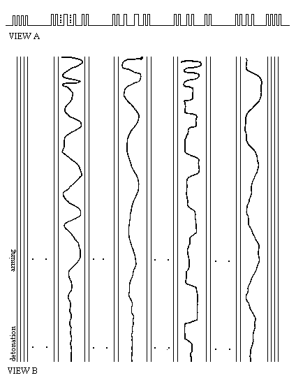
Each channel is marked by a double pulse and the guidance frame is indicated by a four-pulse group. Figure 3-1, view A is a triggered oscilloscope display; view B displays a time versus time display of the system. Note that four of the eight channels are active (i.e., they contain a pulse position modulated (PPM) pulse train). The activity represents guidance for two missiles, two channels for pitch commands and two channels for yaw commands. The remaining channels transmit other commands to the missile, such as command detonation. Guidance is not patterned but can occur anywhere in the channel. In most cases, the guidance pulses do not occur in the 0-10 percent and 90-100 percent channel interval. This is to ensure the command pulses are not mistaken for channel marker pulses. Guidance commands are sent as PPM doublets.

GUIDANCE WITHIN A FRAME
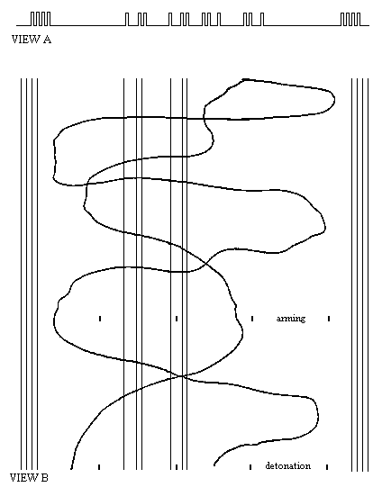
Guidance within a frame does not rely on defined channels to contain the guidance signals. Figure 3-2, view A is a triggered oscilloscope display; view B displays a time versus time display of the system. Note that this system also uses four pulses as the frame marker. The system represented in figure 3-2 shows an inactive mode (i.e., there is no movement of command pulse groups). In this system, there are four triple pulse groups, or triplets, within the frame. Notice the first two triplets have the same interpulse intervals while the spacing common to the last two triplets is different. The difference represents missile addressing. This system uses two pulse groups per missile, one for pitch and one for yaw. In figure 3-2 view B, note the two triplets are able to move over the entire frame. The position of the triplets is determined by the command sent.

GUIDANCE WITHIN A FRAME WITH CHANNELS
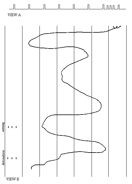
In this format, the missile beacon and missile guidance signals combine to form a composite signal. View A of figure 3-3 is a triggered oscilloscope display; view B is a time versus time display of this system. The missile guidance forms the frame that synchronizes the system. The missile beacon forms the channels within the frame. The two signals are generated from the same source and the phase relationships between them are preserved.

Radio Remote Guidance
Radio remote guidance is the generation of commands onboard the missile. The most common is the beamrider. In the beamrider, the missile follows a directed beam to the target. Equipment in the missile determines the position with respect to the center of the beam, and control commands are generated to maintain a flight axis along the beam center. In another type of radio remote guidance, reference points are established relative to relay devices located on the ground. The reference point system creates a grid on the surface of the earth over which the missile is guided.
Primarily, the field parameter that is used, whether amplitude, time, or phase, determines the operating principle and structure of the radio device in the control system. In amplitude systems, changes in the reception point coordinates cause a change in the amplitude modulation index. In time systems, the position of the missile is determined according to the delay in the received signal. In phase systems, the phase difference is measured.
Homing Guidance
In homing guidance systems, the control commands are generated onboard the missile in response to changes in the position of the target with respect to the missile. Sensors carried in the homing head of the missile determine the target position. The most important function of the missile sensor, usually called the seeker, is to lock-on to the target. Lock on can be automatic or manual. Automatic lock on frees the operator; however, the system may lock-on to a target of less importance or fail to lock on at all. Manual lock on assures the proper target is selected; however, in AAM and ASM applications, where the operator is responsible for flying the aircraft, manual lock on is not desirable.
Homing guidance is normally carried out within the limits of direct visibility between missile and target. There are three methods used by homing guidance—active, semiactive, and passive.
ACTIVE HOMING GUIDANCE
Active homing guidance is carried on onboard the missile and uses radio frequency (RF), visible light, or acoustic waves. The missile contains a computer that predicts the future position of the target and calculates an intercept solution, and a control system that directs the missile to the target. A missile using active homing is autonomous once homing starts. The use of active homing allows the launching platform to break away immediately after launch and concentrate on another target or evade enemy fire. A disadvantage of this system is its limited short range.
SEMIACTIVE HOMING GUIDANCE
Semiactive homing guidance uses a radar to illuminate the target and a receiver onboard the missile to detect the energy reflected by the target. The external transmitter may be located at the launch site or at some distance from the launch site. Semiactive homing systems rely on some external support to provide guidance intelligence. In most semiactive homing systems, a reference receiver is located in the rear of the missile to receive the intelligence signal. Another receiver is located in the homing head. Comparing the frequencies of the signals in the reference receiver and the homing receiver provides an estimate of the target’s Doppler frequency. An important advantage of this system over active homing is the increased range. The major disadvantage is the launching platform must illuminate the target until the missile detonates, leaving the launch platform vulnerable.
PASSIVE HOMING GUIDANCE
A passive homing guidance system directs itself to the target using an onboard receiver to detect and process energy radiated by the target. Passive homing systems can use RF, light, infrared, or acoustic energy. Infrared systems have some advantages over electronic systems because they are usually less complex and the angular resolution and precision is greater.
Autonomous Radio Control
In autonomous radio control, all instruments and control means are located onboard the missile. Autonomous control is normally used to guide missiles to stationary targets or into the general area of the target and then relinquish control to some terminal guidance method. The missile movement parameters are continuously measured during flight by onboard equipment, and flight path corrections are generated internally. Autonomous radio control is called automatic if it is carried out without human intervention. Automated radio control requires some human intervention but allows for a more flexible flight path.
Autonomous positioning is accomplished using radio signals reflected from the earth’s surface. The received reflections provide information about the speed, relative direction, and altitude, or they make possible reception of a radar image of the underlying terrain. The current coordinates of the missile are compared to the planned coordinates, and changes are made to the flight path.
Autonomous radio control imposes no limitation on the number of missiles that can be guided simultaneously. Cruise missiles using this system are launched from great distances, providing a large measure of safety for the launch platform. The disadvantage of this system is the cost of the missiles and also the need to define the missile flight path in advance.
INTERNATIONAL RADAR FREQUENCY BANDS
The international radar frequency bands are referred to by their letter designator. The radar frequency bands with their associated letter designators are shown in table 3-1.
Table 3-1.— International Radar Frequency BandsBAND |
LOWER (MHz) |
UPPER (MHz) |
A |
0 |
250 |
B |
250 |
500 |
C |
500 |
1000 |
D |
1000 |
2000 |
E |
2000 |
3000 |
F |
3000 |
4000 |
G |
4000 |
6000 |
H |
6000 |
8000 |
I |
8000 |
10000 |
J |
10000 |
20000 |
K |
20000 |
40000 |