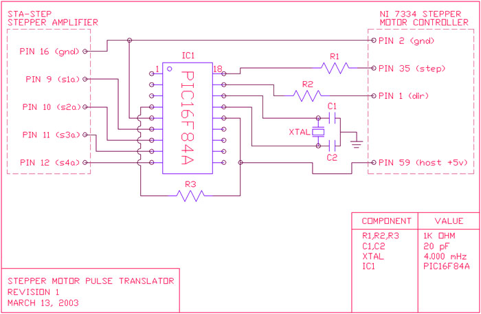
Stepper motor pulse translator July 24 2003
This microcontroller circuit generates pulses for individual stepper motor coils. It was designed to interface NI-7334 stepper motor controller card (PCI) with an older stepper motor amplifier board.
This circuit's input comes from RA0, RA1 pins (pins 17, 18).
Circuit outputs to RB0,RB1,RB2,RB3 (pins 6, 7, 8, 9).Following truth table activates the program:
step pin dir pin action
0 0 nothing 0 1 nothing 1 0 pulse left 1 1 pulse right

Program listing:
; ---------------------------------------------------------
; stepper motor translator
; converts DIR/STEP logic into stepper motor coil pulses
;
; input pins: output pins:
; ra0 = trigger (step pin) rb0 = stepper motor coil s1
; ra1 = direction (dir pin) rb1 = stepper motor coil s2
; rb2 = stepper motor coil s3
; rb3 = stepper motor coil s4
; ---------------------------------------------------------
processor 16f84a
#include <p16f84a.inc>
__config _HS_OSC & _WDT_OFF & _PWRTE_ON
errorlevel -224
; ---------------------------------------------------------
constant TIME = D'20'
; ---------------------------------------------------------
output macro val
movlw val
movwf PORTB
call delay
endm
; ---------------------------------------------------------
; variables
; ---------------------------------------------------------
I equ D'31'
J equ D'32'
K equ D'33'
T equ D'34'
org 0
; ---------------------------------------------------------
; initialize microcontroller i/o
; ---------------------------------------------------------
movlw B'00000011'
tris PORTA
movlw B'00000000'
tris PORTB
clrf PORTB
movlw TIME ; initial delay parameter
movwf T
; ---------------------------------------------------------
; main program loop
; ---------------------------------------------------------
main:
call delay ; account for debouncing
btfss PORTA, 0 ; do we have a trigger?
goto check
goto main
check:
btfsc PORTA, 1 ; going left?
goto going_left
btfss PORTA, 1
goto going_right
goto main
going_left:
call left
goto main
going_right:
call right
goto main
; ---------------------------------------------------------
; pulse left
; ---------------------------------------------------------
left:
output B'00000001'
output B'00000010'
output B'00000100'
output B'00001000'
output B'00000000'
return
; ---------------------------------------------------------
; pulse right
; ---------------------------------------------------------
right:
output B'00001000'
output B'00000100'
output B'00000010'
output B'00000001'
output B'00000000'
return
; ---------------------------------------------------------
; delay routine
; physical time length can be approximated by:
;
; 1_cpu_cycle = (1/(oscillator_frequency/4))
; cycles = ( 9.574 * T^2.6034 )
; delay = cycles * 1_cpu_cycle
; ---------------------------------------------------------
delay:
movf T,W ; reset all counters to T
movwf I
movwf J
movwf K
delay1:
decfsz I,f ; decrement I
goto delay1
movf T,W
movwf I
decfsz J,f ; decrement J
goto delay1
movf T,W
movwf J
decfsz K,f ; decrement K
goto delay1
return
; ---------------------------------------------------------
end