           In AC/DC receivers, the tube filaments are connected in series.
       Since the voltage drop across all the filaments in series may be less
       than the full 117 volts from house's line voltage, it is necessary to
       get rid of the excess voltage. There are three different means for
       dissipating this excess voltage:
           1) Power Resistor
           2) Line-cord Resistor
           3) Ballast Tube

        POWER RESISTOR
           Usually it is an ordinary power resistor getting rid of the
       excess voltage.  Find a replacement with the same resistance and power
       ratings. Higher power ratings can be used for more reliability.
       Power resistor is a good replacement for the hard to find line-cord resistor.

        LINE-CORD RESISTOR
           Usually a two-prong power plug with three-wire line cord.
       The third wire is a resistance element to get rid of the excess voltage.
       Since a line-cord resistor is used in series with filaments, if it is broken
       the radio's tubes will not light up. In some situations it might be possible
       to fix the broken line resistance. When it is not possible, a power resistor
       can be used to replace the damaged line-cord resistor.
           The following steps will help you to find out the specifications needed to
       replace a line-cord resistor for a power resistor.
           (1) Look up in a tube manual the filament volts and current of the tubes.
           (2) Add up their voltages.
           (3) Subtract the total filament voltage from 117 volts to get the excess voltage.
           (4) Use Ohm's law to calculate the resistance (R = E/I) of the power resistor.
           (5) Calculate the power dissipation (P=EI) of the power resistor.
            Example: Radio RCA Moldel 4X3
| Tube Complement
| Filament Current | Filament Volts |
|---|
| 6A7G | 0.3 amperes | 6.3 volts |
|---|
| 6F7G | 0.3 amperes | 6.3 volts |
|---|
| 43 | 0.3 amperes | 25 volts |
|---|
| 25Z5G | 0.3 amperes | 25 volts |
|---|
| Calculations | (1) 0.3 amperes | (2) 62.6 volts |
|---|
| (3) E = 117 - 62.6 = 54.4 volts | (4) R = 54.4/0.3 = 181 ohms | (5) P = 54.4 x 0.3 = 16 watts |
            (6) Thus, 181 ohms and 16 watts are the specifications of the power resistor.
            In practice a 20 to 30 watts resistor can be used to increase realiability.
       If necessary, combine two or more resistors to get the correct values.
       For example, a 300 ohms at 15 watts in parallel with a 470 ohms at 15 watts
       will yield a total of 183 ohms at 30 watts.

        BALLAST TUBE

            Ballast tube is a resistor mounted within an glass or metal envelop and
       connected to a tube base.  This tube plugs into a regular octal or four-prong (UX) type socket.
       Ballast tube, besides dissipating the excess voltage, also compensates for voltage
       variations of the line, making it constant across the load. If voltage increases, ballast
       resistor gets hotter, its resistance goes up, and the voltage drop increases.
       If voltage decreases, ballast resistor gets colder, its resistance drops, and the voltage
       drop decreases.
            Some ballast tubes also have a voltage divider to supply current to the pilot lamps.
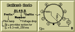
            The RMA code for ballast resistors consists of a prefix of one or two letters,
       a central number, and a sufix of one or two letters.  The number gives the
       total voltage drop, including that across the pilot lamp, if it is the case.
Ballast Resistance Code Table
| Prefix | Indication |
|---|
| B | Ballast action on the pilot light. It may be ommited |
|---|
K
L
M | Type of pilot lamp - 6.3 volts, 150 ma (No. 40 or 47)
Type of pilot lamp - 6.3 volts, 250 ma (No. 44 or 46)
Type of pilot lamp - 6.3 volts, 200 ma (No. 50 or 51) |
|---|
| X | Ballast tube has a four-prong base (UX type). It may be ommited |
|---|
| Number | Indication |
|---|
| Any | Total voltage drop across the resistance, including the pilot lamp(s) |
|---|
| Suffix | Indication |
|---|
| First letter | Circuit arrangement of the ballast tube. See basing diagrams below. |
|---|
 |
 |
 |
 |
|


